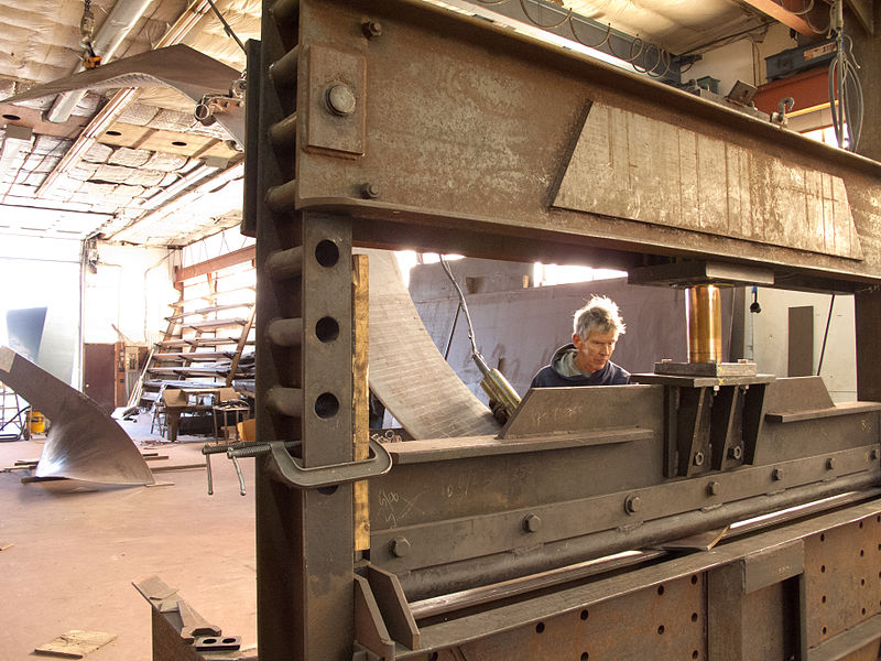
Having options is crucial for metal fabricators because not only they can explore newer techniques and methods but also, they can evaluate their value and efficiency to successfully cut down the production cost while ensuring the quality is jeopardized.
The “options” I am talking about can be anything, from the ability to select the weld pool to choosing between laser cutting and plasma cutting for a project. Even though they might feel very insignificant to the overall project, the importance of having those options is far more important than one would imagine.
For example, if you want to choose a weld pool material, there are few things to think beforehand. The weld pool that you would use in steel fabrication, you might not use for aluminium fabrication, or stainless steel fabrication. Similarly, you might use hydraulic press brake for metal bending or a manual one. It depends on what the project is and what you choose to do. Same goes for stamping, metal rolling, etc. We want choices for all of them.
Sometimes these choices are easy to make and sometimes a bit confusing. One of such choices is picking between powder coating and traditional liquid coating.
Yes, powder coating is not new and many metal fabrication shops are using it already. But like anything in the metal fabrication industry, powder coating is evolving.
I would have picked powder coating anyways but with the new addition of technology and chemical compositions, there’s no way I would choose liquid painting over it.
Why?
Powder coating is efficient
Undoubtedly, powder coating is better and it offers more production value than the liquid coating.
Powder coating is more efficient than liquid coating in 2 main ways.
- Powder coating protects the components better
- Powder coating enhances resiliency
Liquid coating has been on the books for centuries, but in that comparison, powder coating is a much newer addition. The reason why powder coating was introduced is people though liquid coating can’t be the ultimate way to protect your parts and make them look “not rusty” and yes, they were right. Liquid coating is not the ultimate method. Powder coating is far superior in case of protecting the material.
Also, powder coating enhances their resilience. So, it’s safe to say that powder coating is more efficient than liquid coating or painting.
Powder coating emits little to no VOCs
Another great argument for powder coating is unlike liquid painting, powder coating doesn’t emit a massive amount of VOCs or Volatile Organic Compounds. This help the metal fabrication shop in its sustainability program because the VOCs can affect its surrounding greatly.
Powder coating reduces production cost
And lastly, powder coating is a great cost saver for a metal fabrication shop. Unlike other forms or methods of coating, powder coating overspray can be reclaimed and re-use again.
Even though larger particles for powder coating means slower transfer rate, you are still saving a lot and reducing waste. So, it is a win-win situation anyway.
Operational fails are very important in the metal fabrication industry. While these fails are sometimes easier to prevent (like power supply malfunction for the laser cutting, metal rolling machines) and sometimes almost impossible to predict (like a hosepipe leak from a hydraulic metal bending press).
The failures or malfunctions that are almost impossible to predict – can somehow be prevented. But this requires, not occasional, not quarterly, only a routine check, maybe every week, if possible, twice a week.
Whether it is aluminium fabrication, steel fabrication, or stainless steel fabrication, a routine check can save a lot of downtime hours, expenses, and hassle.
For example, say you have your press operator working on a piece. Suddenly he hears a noise and before he could assume what went wrong, the entire lubricating fluid is splashed over him and others who were around the press.
Now, your worker, your machine, the workspace floor is covered in sticky liquid. And if your bad luck didn’t run out already and you have other machine placed close to your press brake, the fluid may also lead into malfunction of those machines.
The question is – how did this could happen?
Maybe you hose pipe broke. That’s the answer for spilled fluid from your press brake.
Now before I get into how you could have prevented it, I should talk about how bad the situation could be in this case, so that you understand why it was important to prevent it.
First of all, you have a broken hose pipe spilling the fluid. You have to take care of the pipe and the press itself.
Secondly, you have your entire floor messed up with the spilled liquid. You’ll have to spare a few of your employees from their work and employ them for cleaning the shop. Also, the people who got spilled by the broken hose pipe, they’ll need to take the day off to clean themselves off.
So what is happening to your metal fabrication shop while some of your employees are busy cleaning themselves and other in sweeping the floor?
Well, first of all, the press failure would cost you a good number of downtime hours. Then, you have the expenses to carry, including replacing the hose pipe, checking if other parts were compromised with the spillage and replace them as well.
So, at the end of the day, you are losing productivity, you are wasting your crew for cleaning the damned floor, you are buying new parts for your machine that were compromised, and above all that, you’ll have to explain why you couldn’t meet your deadline to your clients, which can be intimidating, especially if you are new to the industry and trying to grab as many regular clients you can.
So, the only way to avoid all those things is to regularly check your machines.
If I had to suggest, I’ll tell you to instruct your machine operators to check for any malfunction or displacement before he actually starts working with it. Eventually, this quick checkup will save a lot of downtime and money.
Whether you realize or not, preparation for any metal fabrication process is costly. Sometimes almost half the processing expenses goes in preparation.
Of course, there are laser cutting, metal bending, stamping, metal rolling, etc. that doesn’t require that much preparation beforehand. But welding, painting, coating, etc. needs a lot of attention before you start to work with that piece.
Particularly painting or coating needs a lot of preparation, especially for the surface. The surface preparation can be very expensive but it’s a must. Among all the methods of surface preparation, Abrasive Blasting is the most popular one and it is comparatively less costly than some other advanced methods of surface preparation for painting or coating.
However, some decide to scrap the preparation completely, which leads in not getting the optimal results.
Here’s 3 best practices that could help get the best results and increase the cost efficiency and productivity for Abrasive blasting before you start the coating or painting process.
1. Use the Nozzle properly
There are 2 things to ensure for this part. Number one is “Correct PSI” and number two is “Not overusing the Nozzle”.
The Ideal pressure for abrasive blasting should be at least 100-110 PSI. This is important for better results. However, many do not maintain this standard and using much lower air pressure. This results in unsatisfied finished products.
Sometimes, the fault is your compressor gauge’s because the reading it shows is not always correct. Not that a compressor gauge can’t give you a good reading. Actually, there are many ways for pressure loss during the operation. That’s why you shouldn’t rely on the gauge reading only. In this case, you can use a hypodermic needle style nozzle pressure gauge.
The second thing you need to remember is not overusing the nozzle.
Many think that using an old nozzle for a project won’t do any harm as it doesn’t affect the performance that much. Besides, they get to save a few bucks by not buying or using the new one. But they are wrong. The performance is greatly affected by an old overused nozzle and as for the cost of buying a new one – it’s nothing compared to what other machine parts and maintenance costs.
2. Selection of the Blast Hose
No matter what material you are working with, whether it is aluminium fabrication, steel fabrication, or stainless steel fabrication, using the wrong blast hose will have a dramatic adverse effect on the performance.
Using a narrower one will result in decreased air pressure and performance while on the other hand, using a broader one will cost you more an bring you more hassle to move it around.
3. Selection of the right abrasive
For a blasting project of any sort, the abrasive is a very small percentage of the total cost.
Some abrasive has a lower consumption rate and some blast faster. To determine which abrasive to use, you need to figure out the genuine cost per square foot of the project.
You can use the following formula to determine:
Cost per square foot = Abrasive consumed PNPH x (cost delivered per pound + cleanup & disposable cost per pound) + Labor cost PNPH + (Equipment running cost PNPH ÷ Square feet blast cleaned PNPH)
*[PNPH = Per nozzle per hour]
Ask a metal bending press brake operator “How much you know about your machine?”
Most probably, he’ll say “A lot”.
You might think they don’t want to know anything else as they know enough already, but NO.
Ask a second question. Ask him if he would like some tips or not. The answer will be “Why not?”.
Same for the laser cutting, metal rolling, stamping machine operators and of course the welders.
No matter how much they know, an operator will definitely appreciate some pro tips, especially if it will make things easier for him.
That’s why I publish these tips on my blog post every once in a while and as I did a blog post comparing FCAW and GMAW the other day, I thought why not wrap it up with some handy tips on FCAW and GMAW.
1. Clean the surface well
The first thing you need to remember before you begin the welding process is cleaning the surface thoroughly. It is applicable to all the different types of welding including FCAW and GMAW.
Remember, if you are not doing it properly, you are just ruining your metal fabrication shop’s name and reputation to your clients, which is not good for your business.
Only after cleaning or grinding the surface you should start attaching the work clamp for a solid work connection.
2. Using a sperate circuit breaker
The temperature needed for steel fabrication, stainless steel fabrication, and aluminium fabrication, is different. But regardless of what temperature you need for the material, your machine needs to be connected with a separate circuit breaker which is fused correctly. Otherwise, you won’t be able to produce the amount of heat to melt the material.
3. Avoid gaps
A good fit-up is crucial for satisfying your clients with your work.
For that, you need to minimize the burn-through which can be achieved by avoiding the gaps.
4. Don’t bend the gun cable
For smooth wire feeding, it is important that you keep the gun cable straight. Bending it may cause disruption in the workflow as the current of electricity will be affected by the harsh bend.
5. Tight contact tip
It is important that the contact tip is tightened in the place. A melted or elongated tip can ruin your workpiece completely.
6. Maintaining the correct electrode stickout
I have seen many welders, even the experienced ones to make this mistake. They don’t make sure if the proper electrode stickout is maintained or not. As a result, accidents happen all the time.
7. Drive rolls
The thing with drive rolls is that they must be fed smoothly, with the proper tension of course. If not, the workpiece may not get ruined but your clients won’t be calling you for his next project.
8. Steady hands
Undoubtedly the hands that are holding the welding gun is the most important tool for precise results. If the hands are shaky, no matter how good your equipment is, you’ll only get the worst. That’s why it’s important that the operators hold the gun steady and operate with confidence.
Safety should be the number one priority for any metal fabrication shop. Whether it is laser cutting, welding, metal bending, metal rolling, stamping, the safety of the operators, worker and the machinery is the utmost priority for the manager.
Being one myself, I understand how difficult it is to manage the projects while ensuring the procedure and the operation is risk-free and will be running smoothly. Especially because each machine or process has its own set of safety measure to consider. However, I find ensuring the safety of the welding unit more difficult than others. Not because it’s complicated or a lengthy process. Because people kind of take it for granted.
Welder and even their supervisors are unaware of the fact how hazardous the fumes can be and how to ensure the situation doesn’t get any worse.
3-tiered Approach
Thankfully, there is a three-tiered approach to ensure safety in the workplace and with that, welder and their supervisors can easily prevent any big accidents from happening.
The three tiers
A) Eliminating the hazard, if it is possible
B) Try to reduce or contain exposure to or just render the hazard harmless
C) Equip the employees with necessary protective gears
In stainless steel fabrication welding produced fumes (more than steel fabrication and aluminium fabrication welding fumes) and fumes from other exotic metals can’t be disposed easily. So, a mix of the second and third tiers might be the best methodology.
At the 2nd tier, few specific methods can render these fumes harmless to safeguard the operators or welders.
If the welding operation is happening inside your facility, an exhaust system can evacuate those fumes out of the workplace. In this situation, the plant manager should ensure that the exhaust system is capable of evacuating the unwanted fumes from the place and the toxic fume concentration is maintained below the Lower Threshold Limits.
By using the exhaust system comes the replenishing of the exhausted toxic air, which can be difficult in cold weathers. Also, the unit that is collecting the fume needs to be planted closer to the source of its creation, If the collecting unit is placed far the welding area, the toxic fumes won’t be evacuated efficiently.
But when you are welding outside, the situation is more difficult to handle. In this scenario, you can only rely on the weather to mitigate the toxicity in the air, which depends on the wind flow, temperature, humidity of the air, etc.
The third and last tier is putting the protective gears on. This is the last resort for your employees if the exhaust system in your facility doesn’t work or the weather is not in your favor.
If the toxicity levels are too high or the volumes of the toxic fumes are too much for the exhaust system to handle, your welder should put on masks that have any purification unit in it.
But don’t depend on the gears only. I repeat – this is the last resort. You only need to think about it when you have successfully gone through the first 2 tiers.
Cutting is a process that can be done with a number of tools or machinery. When you cut with a laser, it’s laser cutting, when you cut with plasma, it’s called plasma cutting. Similarly, metal bending, metal rolling, welding, etc. can be done in a number of ways. Some of them have some unique advantages that make it perfect for an operation and sometimes the same features or characteristics is the reason behind the process not being used for a particular type of operation.
This comparison or competition of finishing a process with one of many potential ways is very crucial and confusing in welding because there are so many types and categories of welding.
Two of them are FCAW and GMAW, both being heavily used in small operations and today, I’m going to explain which of them is best suited for small projects in your metal fabrication shop and why.
First, let’s review them briefly.
Defining GMAW
GMAW (Gas Metal Arc Welding) is often referred to by its subtype MIG (Metal Inert Gas) welding. This involves combining metals with a wire, connected to an electrode current. This wire gets through the welding stick that is shielded by any inert gas.
Defining FCAW
Flux-Cored Arc Welding is quite similar to GMAW or MIG, except for the fact that it uses a unique tubular wire filled completely with flux and the shielding gas is not always needed, depending on what filler is being used. FCAW is notable for being extremely inexpensive and easy to learn, although there are several limitations in its applications and the results are often not as aesthetically pleasing as some of the other types of welding methods.
FCAW vs GMAW: General Usage
FCAW
For FCAW, the experts agree that it can be used for aluminium fabrication, steel fabrication, or stainless steel fabrication. However, they recommend that FCAW should be used for materials thicker than 20-ga.
Generally, FCAW is best for thick material with just a single pass. It is also best for outdoors welding. If you have the right equipment and the righty machine, you can easily weld steels up to a half inch thick.
GMAW
While FCAW is best used in outdoors, GMAW has no competition for indoor projects. Experts recommend that welders should use compact 230-V or 115-V-input GMAW wire feeders and machines. The suggested thickness of steel material for the GMAW process is 24-ga to 12-ga. The 12-ga material is slightly thicker than 1/8-inch and the 24-ga material is about 1/16-inch in thickness.
To weld between 1/8 and ¼-inch thick metal sheets with GMAW, operators will need the higher end compact machine that requires 230-V input.
Again, to weld the materials that are thicker than 0.25 inches or ¼-inch, welders will need higher-capacity industrial units.
However, if you are someone who performs most of your welding operation indoor in your closed facility and on clean materials that are thinner than 1/8-inch, a 115 Volts machine is perhaps an economical option a 230 Volts input machine.
Conclusion
So, it is clear from the comparison above that the superiority of FCAW over GMAW or GMAW over FCAW simply depends on the application, material type, and the worksite. Eventually, you will be the one to decide for yourself.
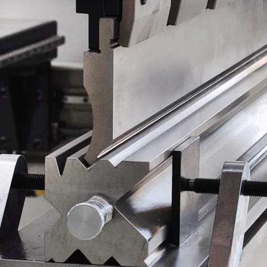
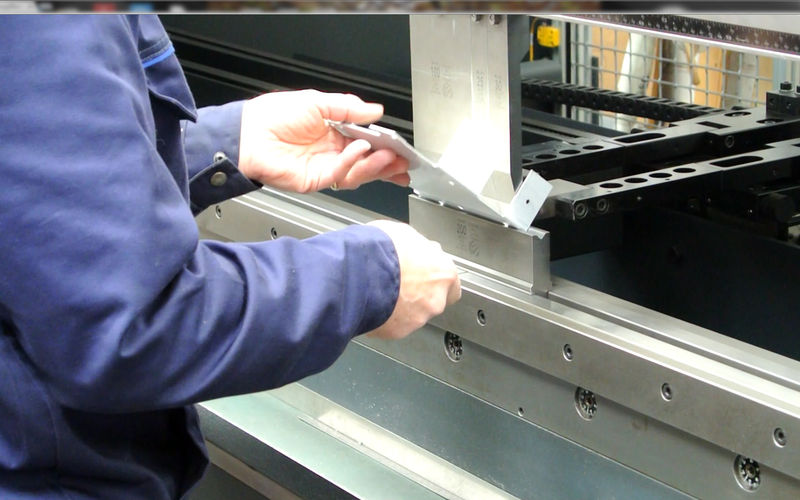
A few days ago, I published an article on the common mistakes in metal bending. Today, I’m thinking of continuing the topic but instead of talking about the common mistakes that we make with all the different kinds of metal bending press brakes, I’m going to dig deep and explain the machine-specific or machine type-specific problems.
Like any machines or equipment used in metal fabrication industry: laser cutting machines, metal rolling machines, stamping dies, welding equipment, press brake machines also uses different sources of power or functions in different ways.
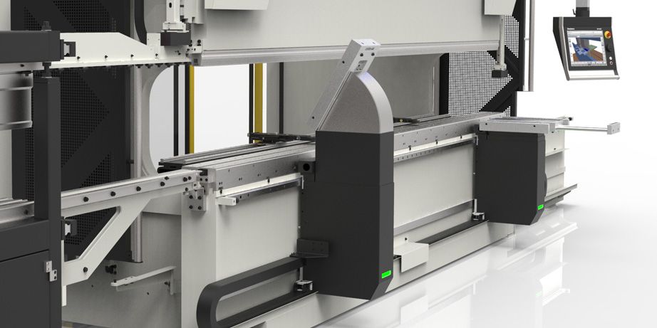
On the basis of how they function, press brakes come in Hydraulic and Mechanical driven form.
Common Mistakes With Hydraulic Press Brakes
Ram Drifting
Every so often, on 2-cylinder hydraulic brakes, accidentally, the ram starts to drift down on 1 or both ends as the machine is stopped with the raised ram and left completely under pressure with the power turned off. This happens usually because of any internal oil leakage in the cylinder.
The leakage can be repaired by replacing the used internal seal and if the situation is worse, simply place a block under the ram.
Adjusting Ram Tonnage Failure
Hydraulic press brakes can either come with the adjustability of the tonnage function or a fixed one. If by any chance you have one with the adjustability option, take full advantage of it.
Firstly, make sure the tonnage is minimum. You don’t want to overconcentrate the load then increase the chances of upsetting the ram or breaking a part of the tooling.
However, if you don’t have adjustability function for the tonnage, you should check in with the manufacturer and find out if there are any retrofit units available to the manufacturer.
Not Changing The Hydraulic Oil
This might seem like an insignificant thing to be reminded of but trust me when I say that you are endangering your cylinders, manifold blocks, and valves by not changing the oil.
If the oil is not changed, it can be contaminated with air, water, and debris. This could also lead to machine breakdown in critical temperature.
Mechanical Press Brakes
Excess load
A clear difference between hydraulic press brakes and mechanical press brakes is the latter one can produce a lot of loads that can be described by my excess load. This excessive load can be 3-4 times the suggested tonnage for the machine.
Not Taking Care of the Position Work
Without taking care of the position work, it is not possible to ensure the suggested or rated tonnage for the operation and this could mess up the integrity of the machine. That’s why it is important that you take care of the position work maintain a healthy setup in the workshop.
Conclusion
Avoiding or preventing these problems will benefit the aluminium fabrication, steel fabrication, and stainless steel fabrication process and the metal fabrication shop in general. So, be careful and if possible, organize a training session for your workers & operators and make them more skilled or capable of handling the machine or the problems.
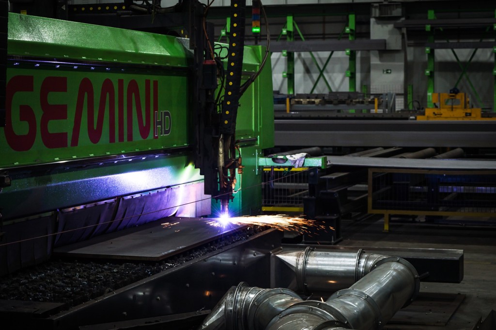
The earlier days of plasma arc cutters were crowned with glories. They were 1000-amp monsters that are designed to cut through 6 inches of stainless steel sheets. However, the unit also went through different phases of development like laser cutting, welding, metal rolling, metal bending, stamping, etc. and if you haven’t upgraded your plasma cutter in a while, it’s time for you to get one and stay up-to-date with your competitors.
But there are a number of things you need to remember while choosing a plasma cutter, like power supplies, gas, cost, components, etc. Today I’m going to explain all the different types of power supplies used in a plasma cutter so that you can get the best one in your metal fabrication shop. I’ll concentrate mainly on the manual ones and leave the automated ones for some other day.
The Power Supplies
Plasma Arc Cutter power supplies are DCEN or Direct Current Electrode Negative. Regardless of the sheet metal material, a PAC needs constant DC source and an OCV (Open Circuit Voltage) which will initiate the arc and prepare it for aluminium fabrication, steel fabrication, or stainless steel fabrication.
Now let’s get into the different types of power supplies.
DC Droopers:
In the early days, plasma cutter used the drooper power supplies. Their name was given due to the drooping power curve outputs and these units are capable of providing a high OCV while ensuring a stable operating voltage and current.
To convert AC power from the transformers into more suitable DC power for the cutting unit, people used fixed-output DC rectifier bridges that consists of diode series. These simple yet powerful systems were able to create a lot of power. However, this system was guilty of wasting a lot of energy. Also, it had too many ripples in the power output which is the fluctuations in DC power output caused by rough cuts or short part lifespan.
In order to regulate the power output even further, different transformers of higher levels of current output could be used.
Reactors:
After the droopers, there was a new era for PAC power supplies, brought by the reactors. The reactors which were used were made of some AC coils and DC winding all around it. These reactors’ AC voltage supply to the bridge rectifier were controlled by reactor devices.
The adjustable transformer created by passing AC through the reactor (controlled by the current in Direct Current Winding) allowed variable outputs of Direct Current from the rectifier bridge.
Silicone-Controlled Rectifiers:
These are a specific type of Continuous Variable DC output supply. With huger transformers and large capacitor banks, SCRs convert 3-phase AC directly into DC.
The SCRs are comparatively large and only used for high-amp PAC systems. However, they are not the best option for manual operation.
Switch-Mode:
These power supplies use the transistors in order to modulate Direct Current power after the rectifier. One of the common types of switch-mode power supplies is the Chopper which uses IGBTs or other semiconductor devices. These Semiconductor devices then take the raw DC with the ripples only to chop it off and switching the power on-off to smoothen the output.
Over the course of time, manufacturers and designers of the stage or progressive tooling has made their peace with projects involving the production of metal stamping. Later on, they will be post-processed with powder coating, painting or plating operations.
This post-production for finish quality is common in aluminium fabrication, steel fabrication, or stainless steel fabrication. The product or parts that come out of plasma cutting or laser cutting machines, metal rolling or metal bending press brakes, or from welding workshop and other machines, are treated in some ways to ensure the finishing is on-point.
Customers’ requirements for post-process finish quality are taken seriously in the metal fabrication industry. But steel tooling can be harsh on the surface. Thankfully, tooling manufacturers and designers are following some simple guideline or tips that are increasing the chances of success.
1. Lifter or Rails
Vulnerable parts may get some benefits if the plunger-like lifters or the lifting rails design uses materials such as Delron® which is like hard nylon. These materials are usually less likely to mar the part surfaces. For instances like – as burr direction, the part specifications need the main part surface to face downwards, protective contact surfaces are very helpful.
For the entire steel lifter units of just the contact points, Delron is a good choice as Delron made lifters along with retention washer, won’t be causing any damage to the die.
2. Position of the parts
In order to minimize the chances of tooling components dragging across the surface, it is important that the part which will be coated is placed in a way that the largest surface stays faced up. For example, any parts that require cosmetic stamping like a computer cover should be positioned in a way that the rails and lifters do not make any contact marks.
3. Die steel & stripper plate sections should be done in a noncritical area
Adie steel or the stripper plates should be sectioned in noncritical areas or scrap areas because if these parts are sectioned in a critical area, burnishing or a kink may occur. Even though it won’t be noticeable in an uncoated part, once the surface is covered, it’s hard to miss it.
4. Avoid through-holes in critical areas
Putting through-holes like screw or stripper bolts holes in critical areas is not a good decision as today’s progressive tooling are very complex and the strippers often employ additional pressures. The additional pressure can cause burnishing at the holes.
5. Surface grinding direction
The direction of grinding is very important for parts like blocks, plates, inserts, etc. All of them should be ground at the same direction.
However, for progressive dies, blocks, plates, should be ground left to right, which allows imperfections in grinding.
The attention is of great importance especially when the tooling is being bottomed for coining or flatness. Know that when the grinding is done perpendicularly to all the grain marks, it is most likely that the grinding marks will be visible after coating.
Any metal fabrication shop had to go a long way to complete a sheet metal-made part for their client. Laser cutting, plasma cutting, metal bending, welding, metal rolling, stamping, etc. require several stages of actions to finish the parts.
But as always, the operators of the machines used for all the aluminium fabrication, steel fabrication, and stainless steel fabrication processes constantly run around in search of some simpler way to get things done instead of such lengthy processes that they have to do over and over again.
Even I was asked a few of them several times. Most common was if there is any way to make double bend easier and be done with in a single wipe bending operation.
The Answer
If I have to pick yes or no to answer this question then I’ll say “yes” for the sake of answering in yes or no.
Actually, there are a lot more than “yes” to answer the question. Keep in mind that when you do the double bending in a single wipe bending operation, you might get a slightly different result than getting the double bend done in multi-stage bending operations.
While bending in one single operation, the operator must pay full attention to get the best die design as well as build techniques.
Producing undistorted bends
When done in a single operation, the parts show strong evidence of flatness loss in a specific area. This distortion or curling is most probably caused the metal deformation as it skids or passes over the main forming radius in the punch. In order to produce undistorted bends, it is important that the amount of deformation is reduced.
Understanding the deformation: Pin & Dough
To understanding the deformation, we can think of a pin and dough.
When a pin is rolled over a flat dough, the dough shows the tendency to wrap around the pin. This is what happens.
Analyzing the deformation
For the dough, the curling or wrapping is a product of continuous strain patterns on both sides. Same for the bending. Also, as the diameter of the pin gradually increases, the curling or deformation decreases.
For the sheet metal, the curl or distortion is caused by the metal skids on the punch point. In this situation, we can compare the punch pin with the rolling pin. Also, metals that don’t go over the punch point are bent into a curved shape and once they are bent, it’s difficult to flatten them.
Reducing the distortion while double bending
To decrease the curling distortion while double bending, there must be some modification made to the lower forming section.
As a part of the lower forming section is removed or relived, the sheet metal is allowed to come closer to the finished position. Consequently, the amount of unbending and bending of the part’s wall is greatly reduced.
This very small yet important change to the machine can have a positive impact on reducing distortion on the metal. Additionally, by increasing the diameter of the forming punch, distortion or curling can also be reduced to an extent.


