
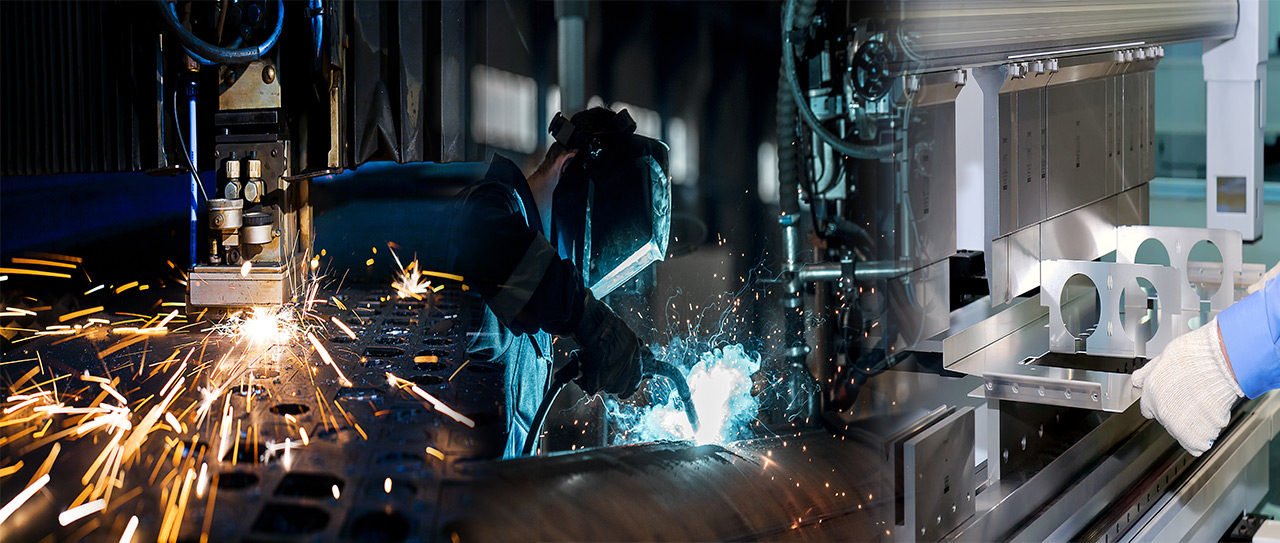

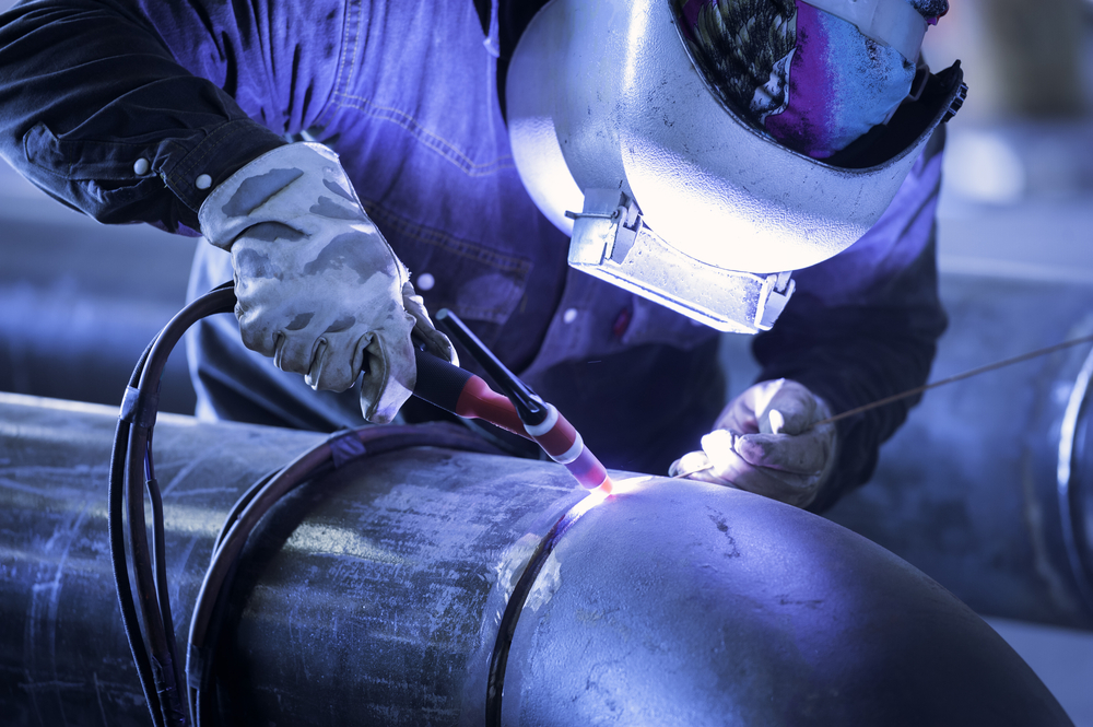
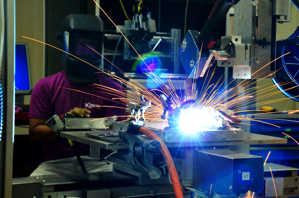
Welding of metal into round pipes or tubes, square frames, boxes, etc. is a billion-dollar industry, known as metal fabrication industry, which had its introduction in the early 20th century. From the beginning of its introduction to mankind, metal bending, welding, metal rolling, cutting, etc. were popular among manufacturers. New methods like laser cutting, Plasma cutting started developing as the importance of metal fabrication grew among people. Very soon stainless steel fabrication, aluminium fabrication, steel fabrication factories were everywhere. Many metal products like fuel line, oil and gas pipe, furniture tubing etc. are fabricated in welded tube mills.

Welding of Steel strip into metal products like, rounded pipes or tubes, square frames, Boxes, structures etc. is a billion-dollar industry, which found its way in the early 20th century. Many metal products like, fuel line, oil and gas pipe, furniture tubing, etc. are fabricated in welded tube mills.
During last 2 decades, OEMs have been applying principals from the tube mills into the gigantic roll forming processing market, which created technology in the same area, known as the welded roll forming.
So what is the main difference between welded roll forming system and tube mill? Which to consider?
But first, you should get familiar with the terms. Traditionally, tube mills are a kind of roll system, which have been fine-tuned in order to run a particular diameter range, mostly at a faster speed.
On the other hand, Welded form systems that include tube mills, welding can occur with the processes like HF (High Frequency) Induction, laser beam welding, electric resistance, HF contact.
In the tube mill, forming machines shape the strip into a circular, weldable item. These forming machines have 2 fundamental parts: breakdown and fin-pass areas. Once welded, the pipe can be left round, however it experiences additionally forming to measure it to a more exact outside distance across. The estimating segment has round move remains with claim to fame reshaping remains toward the exit & a twofold turks-head to finish. Utilized for rectifying, a turks-head has 2 sets of moves, one orchestrated vertically & the second one on a level plane.
Defining the welded roll forming system is somewhat more troublesome. Once more, in the established sense, a tube mill is a sort of a welded roll form system. In any case, on the off chance that somebody alludes to a “welded roll forming system,” he/she is most likely not discussing a tube mill, but rather another roll forming tools ready to frame different, frequently very unpredictable shapes to inside tight resilience.
Like forming in tube mills, with the breakdown & fin-pass segments, welded roll forming systems have a comparative forming setup, with a fin-pass segment happening in the last couple of stands before welding.
While working with non-round shapes, for example, a stage bar, the roll forming system usually frames the structure/shape as it was before the welding. Some in the business call this near-net-shape forming. Other calls this the frame square-weld square process and once that shape is framed & welded, most prescribe no less than two extra passes to work out the welded shapes yet again to finalize the measurements.
For rounded shapes, a tube mill most likely is the best decision. Be that as it may, imagine a scenario where you just need to make rectangles or squares. Imagine a scenario in which you need to have pre-punched openings.
To decide the best machine, think about the qualities and shortcomings of each. Tube mill works in basic shapes. Other than round shapes, they’re equipped for delivering rectangles, squares, and ovals.
In case you’re hoping to frame a couple of entangled shapes, a tube mill might not be the best decision. Forming a few shapes on to the tube mill basically isn’t conceivable, yet a welded roll form mill can frame profoundly confounded shapes promptly.
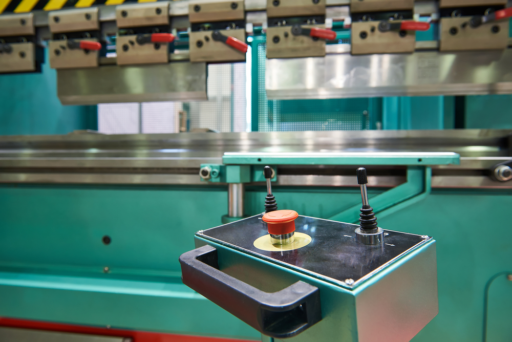
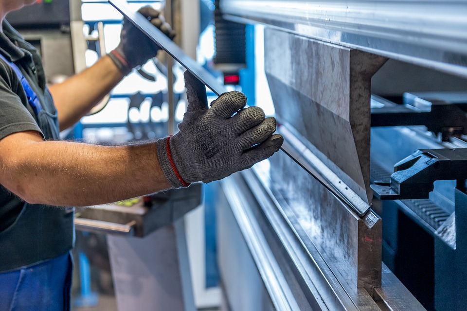
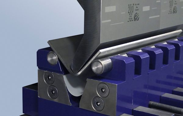
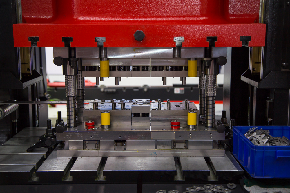
Press brake is a machine to bend metal sheets and plates for specific needs in metal fabrication. These machines are the ones that are used for metal bending the sheets at specific angles for curved and angular use of those metal sheets.
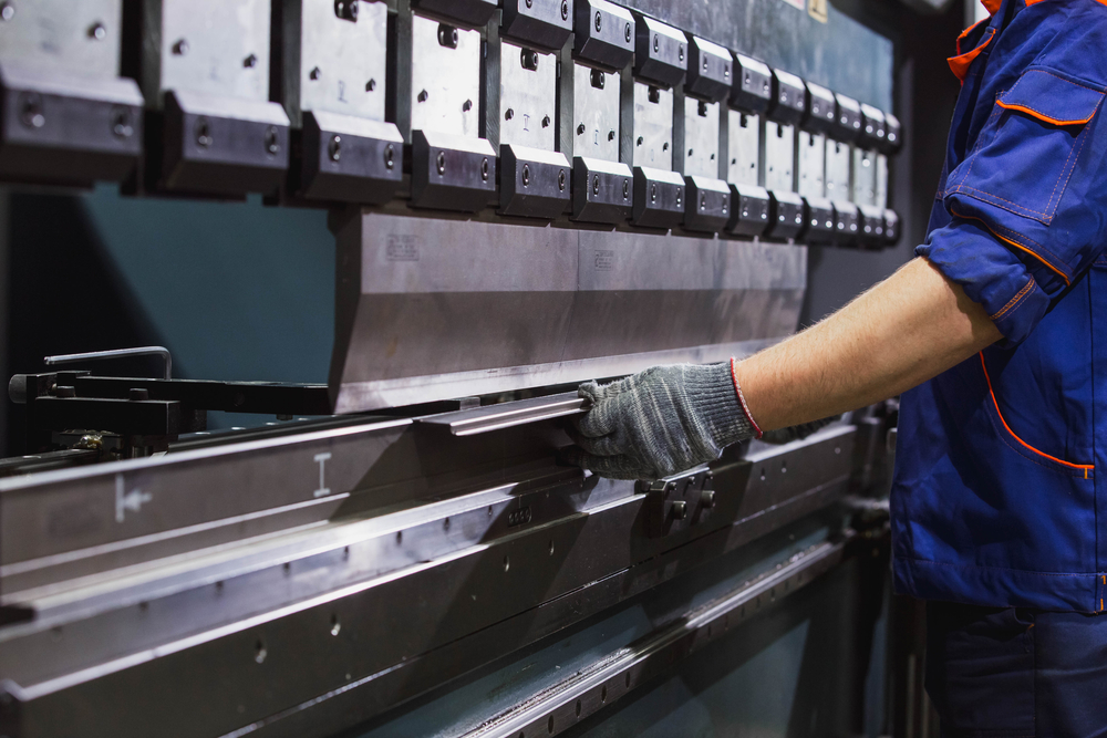
The angles that a press machine can bend your metals are predetermined. Usually, two different C-frames form each side of a press brake. The sides are connected to the table below and on a flexible or movable beam at its top. The bottom side of the machine stays mounted on the table and the top tool stays mounted on the upper beam.
Types of Press Brake Machine
There are 2 major types of press brake machines available for use, Mechanical and Hydraulic.
Mechanical: In a mechanical press brake, a big flywheel spins at high velocity. Once the operator engages the clutch via pneumatic, the flywheel is mated to the crankshaft with which the Ram is attached. Then the crankshaft spins the ram up and down. This is how mechanical press brake machine functions.
The advantages of this type of mechanical press brake is that they are electronically simpler. The mechanical ones are perfect for punching application because the shock of the punching materials is equally distributed, thanks to the machine’s design.
The main disadvantage of the mechanical ones is that the ram needs to complete a full stroke or cycle and usually can’t be reversed while the process of bending is happening. And to operate a mechanical press brake, a heavily skilled operator is a must.
Hydraulic: In these press brakes, hydraulic pressure is passed from the cylinders to force machine’s ram down. The hydraulic controls of machine, ram accuracy of the press brake are more precise than mechanical brakes. The number of cylinders controlling the press brake varies machine to machine.
The hydraulic ones utilize the electrohydraulic control, which is based on linear control systems and measurements. This provides precise and reliable operation in metal sheet work. However, hydraulic press brakes are comparatively expensive but they are safer than the mechanical ones.

Applications of Press Brake Machine
Shaping, bending, and curving metal sheet with press brake is a kind of art, which is vastly dependent on the operator and his skills. That’s why its application may vary for two different operators. But here are some basic universal application of Press brake machine:
Sheet metal bending: It’s obvious that press brake machines will be used for sheet bending the most. The resultant product can be used in different manufacturing industries.
Home appliances: Press brake machines can be useful for making the structure for different home appliances.
Vehicles: The structural bodies of a car, bus, train, etc. have many curves and angles. It is important that the angles are précised and that’s why press brakes are used in the vehicle industry.
Heavy Industrial Machine: Many industries have gigantic machines with a bulky cover body. These are shaped with press brake machines for saving time and effort.
Press Brake Tooling
To ensure that the Press brake works properly each time when you punch and select a dye, it is important to check the tooling tolerance. But for the best and smooth result, using correct die is the most important thing. Here are some common dies to choose from.
- Curling Dies: This die is used for coiling or curling metal sheet edges.
- Multiple bend dies: These dies are made for specific shapes. They can form multiple bends in 1 motion, depending on your project requirement.
- Offset dies: For “Z” shaped two-angled formation, offsets dies are suitable.
- Seaming dies: For creating seams in metal tubes and sheet, seaming dies are used.
- Acute-Angle dies: These dies are used for specifically right angle and acute angle. But they can form obtuse angles in the metal sheet.
- V-Dies: For “V’ shaped angles, V-dies are used in a press brake.
- Gooseneck dies: These dies are used for clearing flanges.
- Rocker type dies: They can bend metal by moving back and forth or up and down.
Types of Bending
Two major categories of bending sheet metals are described below.
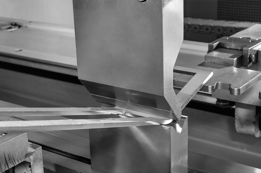
Bottom Bending: It is a simple operation of the punch or tool that is mounted in the ram of press brakes. In this type of bending, the workpiece is forced down in the bottom of dies, which is mounted to the bed over the press brake. Typically, the tools is forced slightly closer to its die than sheet’s thickness. The overbending “coins” the metal and uniformly “seats’ the bend.
The advantage of this bending is that the accuracy of bending depends mostly on the tools itself, rather than largely on the press brake.
Air bending: Air bending is a simple process of pressing down material into the die, just enough to achieve your desired angle. The material isn’t pressed up to the bottom of die, which leaves an air gap.
It is preferred between the two different bending types because in this method, the die needs to change only when the thickness of material is changed. But the main disadvantage of air bending is that the bending accuracy vastly depends on material thickness.
How can Press Brake Machine achieve high precision?
Precision bending came a long way in recent decades. What was considered “precision” in the 80s wouldn’t even pass the muster nowadays.
Although today’s press brake machines are far more advanced than the ones in early 2000s, the precision is not quite there that one would have expected. Here are few variables that can be the reason why the precision is not up to mark.
Machine variables:
- Total time the material is held under the load
- Ram repeatability of machine
- Deflection of side housing
- Ambient & oil temperature
- Deflection of ram and bed
- Response time of filling valves of hydraulic machines
Tooling variable:
- Wear of the die and punch
- Proper alignment and seating of the tooling
- Dimensional tolerance of die, die holder, and the punch
Material variable:
- Spring back
- Material’s protective coating
- Surface hardness
- Material thickness
- Gain direction of the metal during formation
- Homogeneity of material, especially their yield strength
To achieve higher precision:
Proper tooling is a must. No matter how accurate the press machine is, if the tooling isn’t done properly, maximum precision can’t be expected. That’s why the press brake machine you are about to use, must be equipped with proper tooling.
Skilled operator should be recruited. Although it is true that nowadays, the press brake machines are smarter and even a low skilled operator can get the job done, it’s wise to have someone around the machine who is well aware of what he’s doing.
Ram repeatability. Ram repeatability is an important factor to consider if you want higher precision. So, it’s important to keep that on the mind.
Conclusion
Although a press brake might seem a simple machinery for your factory, but like most of the machines in stainless steel fabrication,
aluminium fabrication or steel fabrication, it’s much more complicated than you’d think. That’s why it is important to know how it works and what type of press brake or which type of bending is suitable for you. Remember, in order to achieve high precision, there is no alternative to caring about even the smallest detail of the machine, whether it is laser cutting machine, Metal bending press brake or metal rolling machine.
If you are familiar with metal fabrication and very often get to see sheet metal bending your own eyes, you may notice a slight thrust from the sheet metal after the press brake machine is done enforcing it with a specific pressure. This is called springback by metal fabricators.
What is Springback?
It is more like a pushback from the material itself than a thrust. This pushback from the material is caused by its elasticity. In simple terms, elasticity is the natural characteristic of an elastic material that leads a distorted object to try to achieve its previous form to an extent when the force is withdrawn from its body.
Due to the elasticity of sheet metal, it tries to get back its previous form before the metal bending and this is how we get springback from sheet metal. So Springback is actually a geometric change that happens to a part of the sheet metal when the metal bending is done and the sheet metal is released from the force of the press brake machine. In a sense, it is just the metal trying to spring back to its original shape and thus the term Springback.
Is it possible to predetermine the Springback?
Although calculating the spring back is extremely difficult, it is not impossible in any sense.
There are few factors to consider while estimating the springback. First of all, fabricators should know the Modulus of Elasticity (MOE), which is known as Young’s Modulus. This is an important factor to predict distortion and elasticity. Apart from Young’s modulus, you need to know the included bend angle, material thickness, bend radius, K-factor, and the yield strength.
Calculating Springback
Although this might seem like extremely tough, especially when I’m bombing you with all these geeky factors, actually, it is not. Fabricators don’t even need to calculate the MOE, Yield Strength, and K-factor. They will be available online because they are almost constant for specific material. You just need to put it in these equations.
V = (Ir×Y)/ (MOE×Mt×1000)
Sf = [4× (V2)–3] ×V+1
Ra = Ir/Sf
Af = [{Ir+ (K × Mt)} ×A}]/ {(K×Mt) +R}
Sd = Ir–Af
|
Symbol |
Meaning |
Unit |
| K | K – Factor | Decimal |
| Y | Yield Strength of Material | PSI |
| MOE | Modulus of Elasticity | KSI |
| Sd | Springback | Degrees |
| Sf | Springback factor | n/a |
| A | Angle before springback | Degrees |
| R | Radius after the forming process | Inches |
| Ir | Expected Inside radius | Imperial Decimal |
| Af | Final Bend Angle after springback | Inches |
If the equation is filled with proper values of Young’s Modulus, K-factor, Yield Strength, Angle, Final Angle, and Inside radius, you will be able to determine Springback, Final angle, springback factor, etc. no matter what you are doing this for, stainless steel fabrication, aluminium fabrication or steel fabrication.
Although they won’t be 100 percent accurate, they’ll give you a close estimate and if you are somehow related to metal rolling, metal bending, laser cutting or any type of metal fabrication process, you’ll need as much statistical and analytical help as you can get.
So, now that you know calculating springback is possible, you can easily determine the outcome and take precautions likewise.
Adhering to safety measures for metal fabrication enforced by the American National Standards Institute has been a priority for both hydraulic press builders and owners. Whether it is stainless steel fabrication, aluminium fabrication or steel fabrication, these safety measures are a must for all, regardless of what kind of services you provide. However, in light of a recent possibility of relaxing some of the regulations have brought into question whether or not obsolete safety regulations are that important. Ideally, having a zero risk work environment should be the goal, but installing functional and expensive safety equipment adds to the cost of manufacture by a great amount, especially if the press needs a refurbishment. Therefore, how much should presses compromise in order to satisfy both parties?
Expert opinion:
Experts have commented on the feasibility of maintaining the high safety standards set by ANSI on the presses. Additionally, they’ve argued that it is extremely costly for customers to make investments due to the high costs of safer machinery. However, they’ve proposed that since ANSI rules have a buffer period before being accepted by the OSHA (, industries can have some breathing room when making necessary changes to meet the new standards that they will soon be federally required to follow. Moreover, if given enough time, presses might come up with smarter solutions and implement them into the press.
There are issues however when it comes to reinstalling safety features into older machinery, mostly due to the cost but also because the original machine was not designed to house the new extra safety equipment required to support a load-holding system.
What are the preventive measures?
There are some primary focuses when it comes to all this which is figured out by means of a thorough risk assessment. This will evaluate how extensive the safety measures incorporated into the system must be. There are three main concerns depending on the size of the load:
- A monitored mechanical loading system is required.
- A hydraulic load holding system is required.
- A combination of both of the above.
The risk assessment criteria will account for the size and shape of the safety hazard in addition to the forces working on it. Additionally, each of the load holding systems must be capable of independent and automatic operation on separate loads.
There are two main systems where this can be implemented:
- Single cylinder systems: If the cases arise where the risk levels are above unacceptable levels, then, the hydraulic press must consist of a separate configuration that holds the load in the event of a failure by using return cylinders and a monitored valve.
- Multiple cylinder systems: In this case, two monitored valves placed in close proximity to the cylinder outlets of the two main cylinders or two separate return cylinders that aid in stopping the load from becoming a safety hazard.
An additional step is taken where the individual load holding systems are interconnected preventing a full shut down of the press in the case of failure in any part of the system.
Conclusion:
If all of these extra measures are taken in laser cutting, metal bending, welding, metal rolling, and other fabrication process, fabricators will face lower risks and hopefully satisfy ANSI. Given the time before OSHA makes these changes obligatory, presses have some time for experimentation.
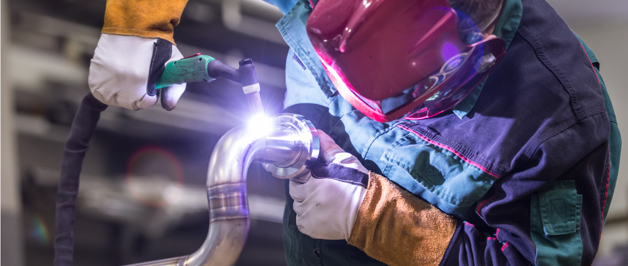
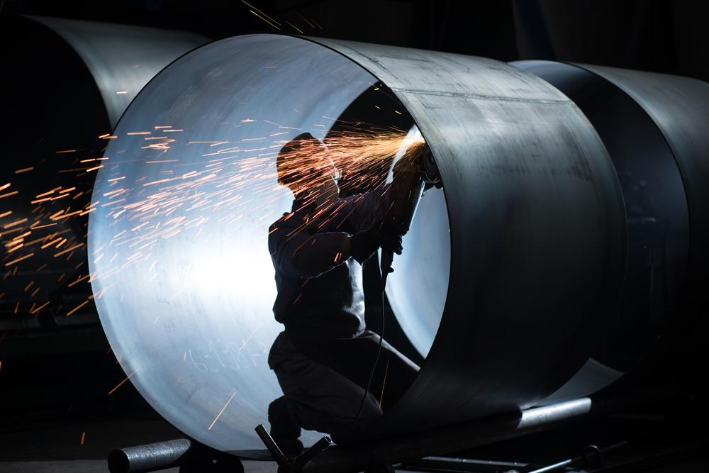
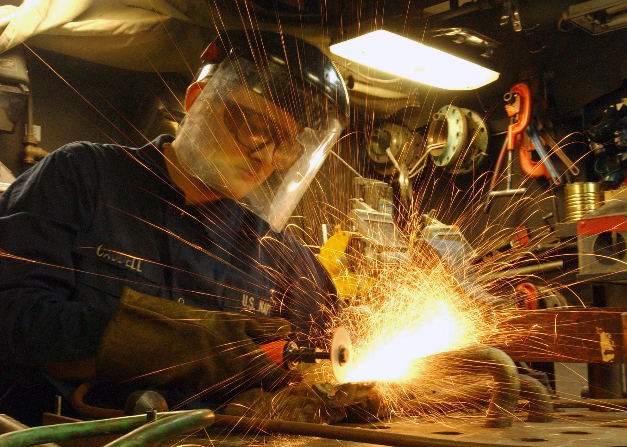
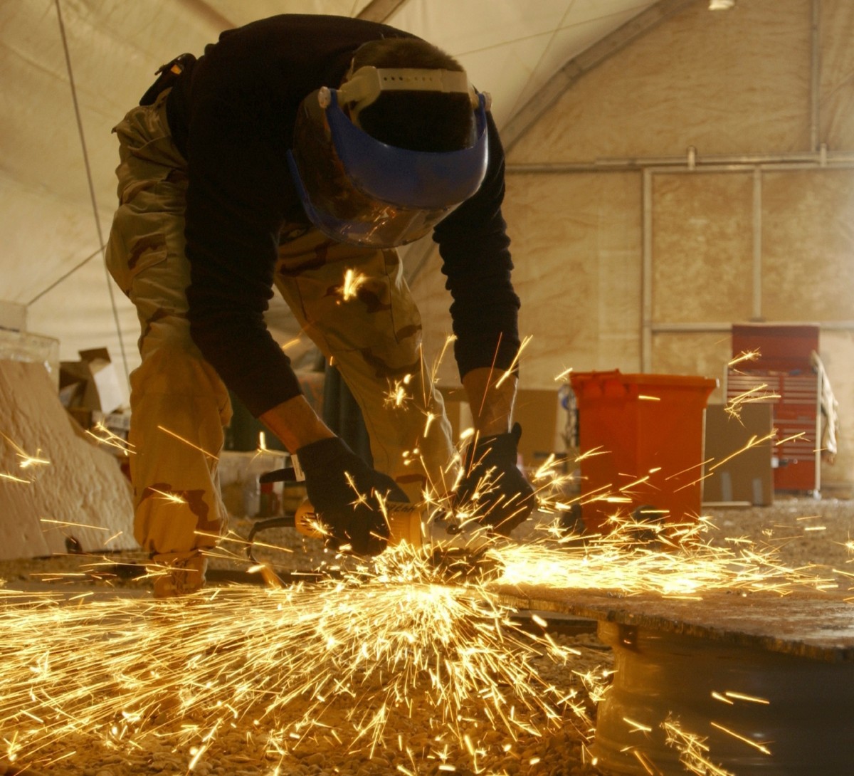
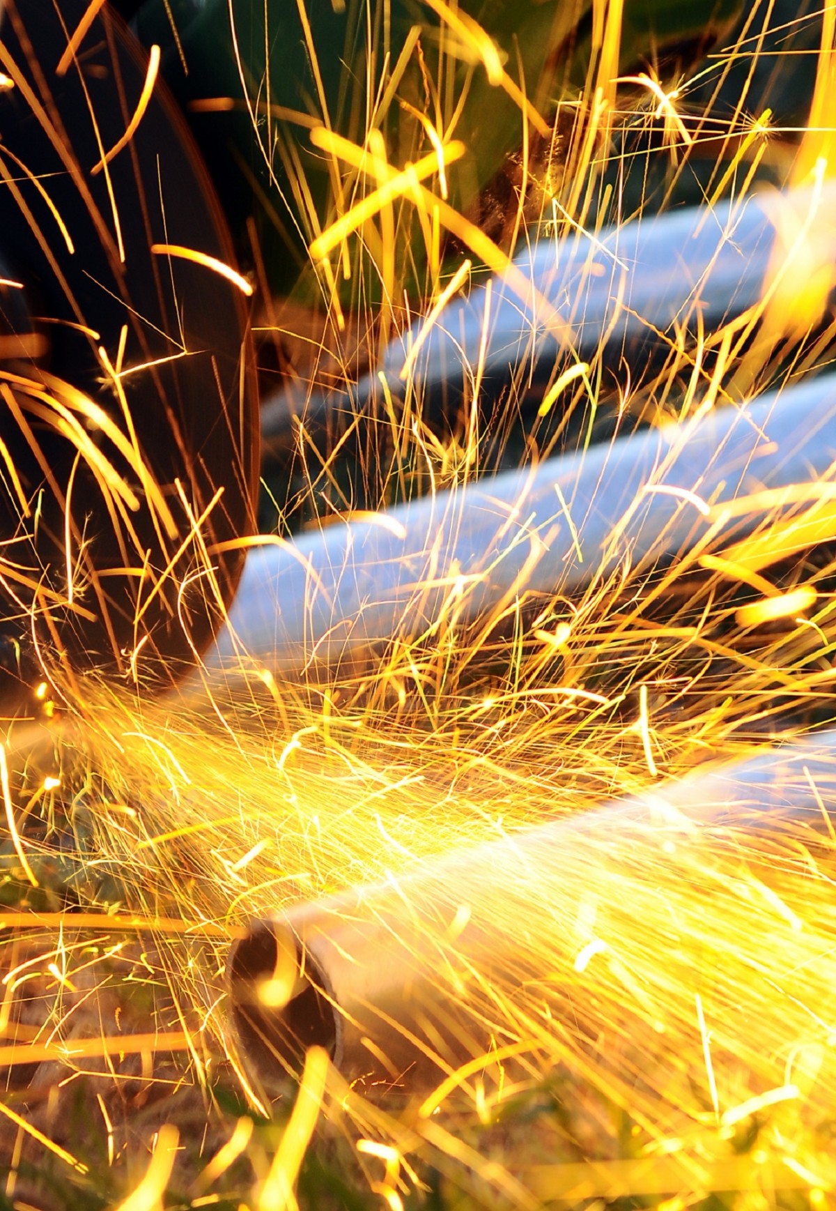
You will never hear from a kid that one day he will become the wielder of a grinder in a metal fabrication workshop or out in the garage. Some people may enjoy it, others loathe it, but no one can deny that grinding is an old and manual fabrication process, even older than laser cutting, metal bending, welding, metal rolling, etc. Besides, it is difficult to avoid. No matter what you are doing, stainless steel fabrication, aluminium fabrication or steel fabrication, the surface needs to be neat and bevel needs to be cleaned out as welding preparation. Some fabricators use torches for welding preparation but usually, they need to get a pass or 2 with angle grinders.
But when it is time for beveling, the hand grinding is not the prime option. There are many power tools with beveling options that involve any type of milling or nibbling cutter. Some of them come with a guide that helps position the tool along the surface edge. Like milling operation on the machining center, the beveling tools can create chips which carry away the heat produced for operation, avoiding heat-affected regions created by the thermal process.
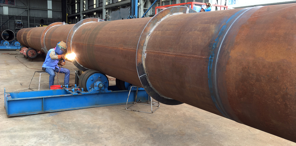
There is a specially designed beveling tool, suitable for pipes. It is the B-500, which is a single-pass metal pipe beveler manufactured by RIDGID®, a part of the Emerson Commercial and Residential Solution.
This system is designed to be easily moved to the work site, be it in the sea or the field. Besides, the tool doesn’t have any mandrel, which engages the pipe’s inside diameter. Global marketing manager of RIDGID, Mr. Larry Feskanich told that it had no bulky pieces to be carried along for mounting inside the pipe’s diameter. He also added that any specific accessory is not required to adapt to different pipe diameter of pipes. Instead, it will grip pipe’s wall between 3/16 inches and ½ inches thick with 2 wheels standing on the (OD) outside diameter. Another wheel is in the ID (inside diameter). These wheels can easily adapt to any pipe with 4 inches outside diameter and more, all the way to flat plates. It should be noted that a wheel does need to be fit to the inside of that pipe so that the tool is not designed to bevel pipes smaller than 4 inches in diameter.
Few beveling units available on the market is capable of peeling a ribbon off the edges by using a cutting action, which resembles a can opener. Other tools use nibbling tools with square or rectangular punches, which moves up and down.
Also, there are some which use a milling cutter, including the B-500. Once the tool operator clamps it, the cutter sits in the parallel position to the pipe. Once this system is engaged and its cutting head starts to mill away, a beveled edge is created based on the tool’s geometry. This way, its cutting head governs the required bevel angle. One of the cutters creates 30 degrees bevel and the second one creates 37.5 degrees. The last one makes the 45-degree angle on the bevel and all of them are designed to make the bevel with a single pass.
It’s claimed that it will shorten the welding preparation period drastically, making welding as quick as possible so that daily production is increased.
Metal fabrication is all about precision. No matter what it is, laser cutting, metal bending, metal rolling, grinding, boring or welding, metal fabricators need to be “precise” and “on point” to get best-fabricated products from his workshop.
Precision is the weapon for fabrication industry and they can’t risk missing any details unless they want to leave a bad impression on their clients, which is definitely not profitable for him. And it is never late to check the details. Fabricators have literally endless time to look for the missing details and modify accordingly till it is being shipped to the client’s address.
But it may be confusing if I keep referring to “details” without explaining what I’m actually indicating towards. Actually, I’m talking about everything with the word “details”.
This “details” is the measurements that you take for the stainless steel fabrication, aluminium fabrication, or steel fabrication job that a fabricator has in their hands. They should ensure the angles are properly measured, the lengths are accurately calculated, and the force or pressure is applied exactly according to the requirements. Simply, every variable and its value in metal fabrication industry is a “details”. You must make sure the details are on point.
Another thing that I mean when I say “details” is the intensity of that pressure. Think it like boiling an egg. Some like half boiled and some want their morning egg to be hard properly. Although the process of preparing half and full boiled egg is same, the difference is in the intensity of water heat and time. Just like this, every metal fabrication process has multiple resultant to offer. It depends on the intensity of the process to give you precise results. That’s why you can’t miss out any of them.
The last thing that falls under the category of “details” in metal fabrication is the miscellaneous works that come with every fabrication job. For example, cleaning the edges before grinding the second time, making sure the welding is not too thin, etc. are the type of work that fabricators don’t want to pay too much attention to. But little did they know that small things like this contribute immensely to the success of a product.
Fabricators should understand the importance of this small details every time they start a new project until they have shipped it away successfully. True success in fabrication industry means your client is satisfied to receive what he wants and you are satisfied delivering it to him.
Even the littlest, most apparently unimportant things, such as neglect cleaning or supplant your consumables, could heighten to finish machine glitch. Missing even a little spot of slag between the passes will leave an incorporation that could prompt a weld breaking out. Also, an erratically prepared tungsten may make them ask why the TIG puddle is everywhere.
It’s never past the point where it is possible to chip away at the little things, and they really do mean achievement in bigger things as you advance in the exchanges. Scrupulousness isn’t something that simply happens. It’s an educated quality, and you’ll have it just on the off chance that you set it in motion on the very beginning.
You will never hear from a kid that one day he will become the wielder of a grinder in a metal fabrication workshop or out in the garage. No one will say that I want to be a laser cutting machine operator or metal bending and even metal rolling specialist. Some people may enjoy it, others loathe it, but no one can deny that grinding is an old and manual fabrication process and it is difficult to avoid. The surface needs to be neat and bevel needs to be cleaned out as welding preparation. Some fabricators use torches for welding preparation but usually, they need to get a pass or 2 with angle grinders.

But when it is time for beveling after the process of stainless steel fabrication, aluminium fabrication or steel fabrication, the hand grinding is not the prime option. There are many power tools with beveling options that involve any type of milling or nibbling cutter. Some of them come with a guide that helps position the tool along the surface edge. Like milling operation on the machining center, the beveling tools can create chips which carry away the heat produced for operation, avoiding heat-affected regions created by the thermal process.
There is a specially designed beveling tool, suitable for pipes. It is the B-500, which is a single-pass metal pipe beveler manufactured by RIDGID®, a part of the Emerson Commercial and Residential Solution.
This system is designed to be easily moved to the work site, be it in the sea or the field. Besides, the tool doesn’t have any mandrel, which engages the pipe’s inside diameter. Global marketing manager of RIDGID, Mr. Larry Feskanich told that it had no bulky pieces to be carried along for mounting inside the pipe’s diameter. He also added that any specific accessory is not required to adapt to different pipe diameter of pipes. Instead, it will grip pipe’s wall between 3/16 inches and ½ inches thick with 2 wheels standing on the (OD) outside diameter. Another wheel is in the ID (inside diameter). These wheels can easily adapt to any pipe with 4 inches outside diameter and more, all the way to flat plates. It should be noted that a wheel does need to be fit to the inside of that pipe so that the tool is not designed to bevel pipes smaller than 4 inches in diameter.
Few beveling units available on the market is capable of peeling a ribbon off the edges by using a cutting action, which resembles a can opener. Other tools use nibbling tools with square or rectangular punches, which moves up and down.
Also, there are some which use a milling cutter, including the B-500. Once the tool operator clamps it, the cutter sits in the parallel position to the pipe. Once this system is engaged and its cutting head starts to mill away, a bevel edge is created based on the tool’s geometry. This way, its cutting head governs the required bevel angle. One of the cutters creates 30 degrees bevel and the second one creates 37.5 degrees. The last one makes the 45-degree angle on the bevel and all of them are designed to make the bevel with a single pass.
It’s claimed that it will shorten the welding preparation period drastically, making welding as quick as possible so that daily production is increased.
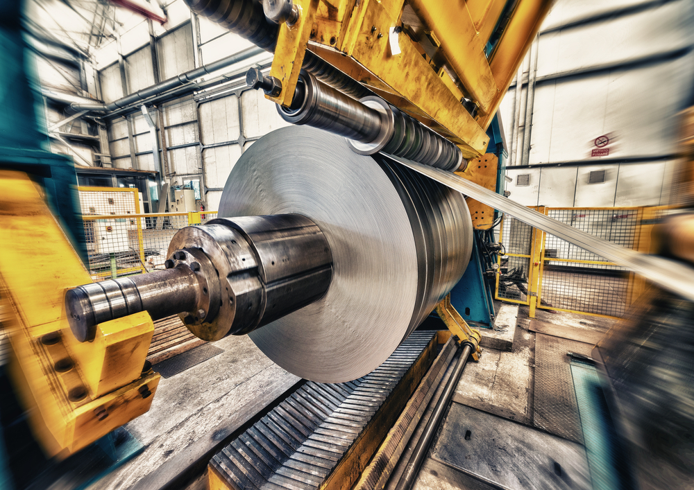
The global steel production for metal fabrication has made their journey into the sky for ten years straight from 2005 to 2015. But in 2016, the trend seems to get a pause. After 2015’s marginal growth, output dropped 3% that is 164 million tons globally in the year 2016, as mentioned in the annual report by German Steel Tube Association. But thankfully, last year’s production brought a new hope for the industry. According to WorldSteel.org, last year’s crude steel production was highest among previous years’ worldwide steel production. Previously, the record production of crude steel was in 2014 where China alone produced 822.3 million tons and the rest of the world produced 847.1 million tons, making the total production of steel around 1670 million tons. But in 2017, the production leaped a slight from 2014s 1670 million tons to 1691 million tons, where China alone produced 831.7 million tons and 859.5 million tons from rest of the world.
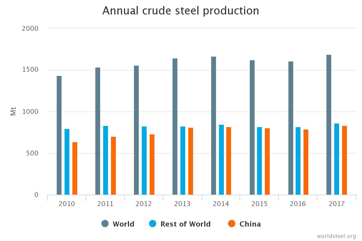
Source: WorldSteel.org
This rise of demand was caused by continuous use of Steel in stainless steel fabrication and steel fabrication. These steel is used for metal bending, laser cutting, manufacturing metal cabinets, boxes, metal rolling, etc. With the massive use steel, aluminium use for aluminium fabrication is also increasing rapidly. But that’s not what I’m going to cover today.
Anyway, when people asked about 2015’s drop in steel production, many came to the conclusion that it was caused by an attempt of replacing steel with other metal throughout different industries. Although the motive was to find out another metal that is more efficient and cheap in price, clearly the motive wasn’t fulfilled and we could say that from 2017’s rise in demand for steel in the global market.
This demand was scattered throughout all over the world, in different industries. As usual, the Building and Infrastructure industry had the most demand for steel. They consumed almost 50 percent of total production worldwide. Second in place for steel craving was Mechanical Equipment industry that consumed total 16 percent of annual steel production. Here the difference between Building and Infrastructure to Mechanical Equipment demand was huge. But with 13 percent consumption and demand for steel last year, Automotive industry is close to the Mechanical Equipment industry, in terms of using the steel.
On the fourth position, Metal Products kept their feet grounded like every year, using almost 11 percent of total steel production last year. From here on, other industries divide the demand between themselves according to their need. Most notably, other transportation systems is consuming 5%, Electrical Equipment 3%, and Domestic appliances 2% in total.
An Assumption
According to the claims of German Steel Tube Association, Steel pipe industry and its application have improved since the year 2016. The estimate indicated that the overall investment in energy sectors will surely get back to normal from its state after 2015’s sudden fall.
Additionally, the resulting backlog, the circular upswing in the raw metal material and steel rates should benefit the industry like the continued robust economic activity is benefitting the industrialized world. Apart from that, the German Steel Tube Association is expecting North America’s expansive economic policies and the energy policy to put a strong focus on the fossil fuels. This will have a positive effect on the steel tube and pipe industry.
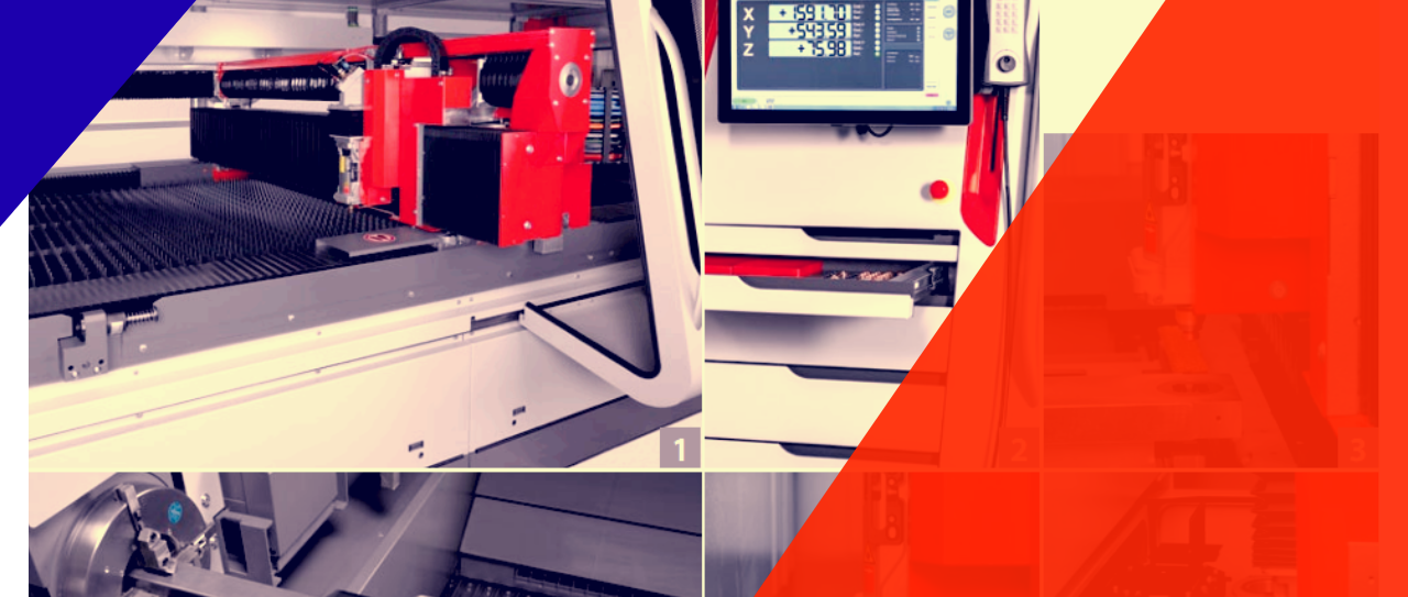
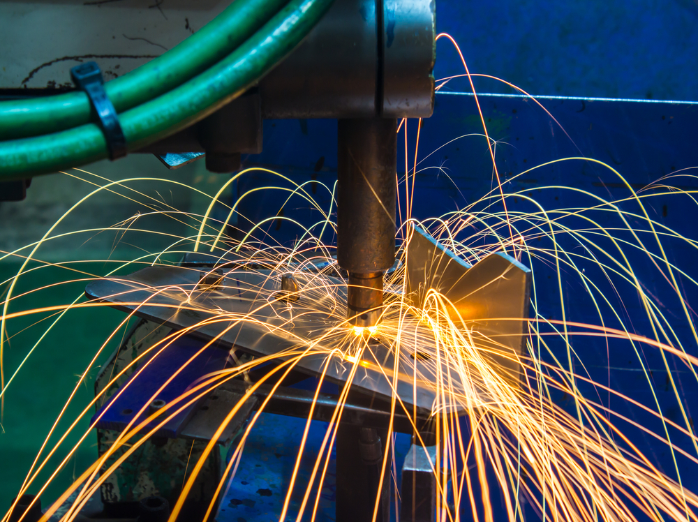
Manufacturing process nowadays is very safe and efficient thanks to the advancements being brought every day to the metal fabrication industry. This technological advancement has brought back the desired industrialization that people hoped to see after the Industrial Revolution. Laser cutting, metal bending, metal rolling and almost every stainless steel fabrication, aluminium fabrication, and steel fabrication process have brought new dimensions to the metal fabrication industry over the years. These inventions and advancements have made the industries profitable and the one which made the best out of it is the laser.
Laser technology made an impact so big that none of the others were even close. Its impact can be felt throughout the entire manufacturing industry, not only for its cutting ability but also for its welding feats too. New and proficient generation forms are frequently impractical without the upsides of laser innovation. Along these lines, assorted sheet thicknesses and characteristics are transformed into custom-made spaces by welding and protection spot welding is supplanted by laser seams.
Laser welding has almost become paradoxical in how efficient and flexible it is compared to the weld joint geometries. When the fabricators can consider how restrictive and bound the requirements are for the highest possible gap, they’ll easily know why. Although it is true that maintaining a minimal gap seam in important for broad range of ways for assembling a part for laser welding, it is immensely beneficial to consider its effects on the upstream processes.
Today’s modern laser is capable of cutting metal parts more consistently, quickly, and with clean edges. With the laser welding, fabricators can achieve higher speed for welding that results in a weld seam. The part is finished when the weld work is finished.
How does it work?
Laser welding can be done by hand but most of the systems are automated these days. These systems use Computer Aided Manufacturing (CAM) which is based on the Computer Aided Designs.
The laser beam welding is for the most part utilized for joining segments that should be attached with high welding speeds, thin and little welding seam & low thermal distortion. The higher welding speeds, a phenomenal programmed task and the likelihood to control the quality online amid the procedure to make this laser welding a typical joining technique in the cutting edge modern creation.
Laser types
There are different types of laser available for commercial use, but mostly two of them are used for laser welding. They are Solid State Laser and the Gas Lasers.
Solid State Laser operates at specific wavelengths on the order of one micrometer, which is much shorter compared to the gas lasers for weld works. The gas laser uses high voltage and low current power source to supply just the amount of energy needed to excite that gas mixture that is used as a lasing medium.
Laser Welding Machine Type
Modern-day laser beam weld machines can be grouped into 2 major types. The traditional type and the remote type. In the traditional types, the laser output is moved to precisely follow the seam and it is mostly done by a robot.
In Remote laser beam welding, the laser output is moved precisely with the help of the laser scanner. This laser welding machine has many advantages over the traditional ones. But the higher precision and speedy finish are the most noticeable ones.
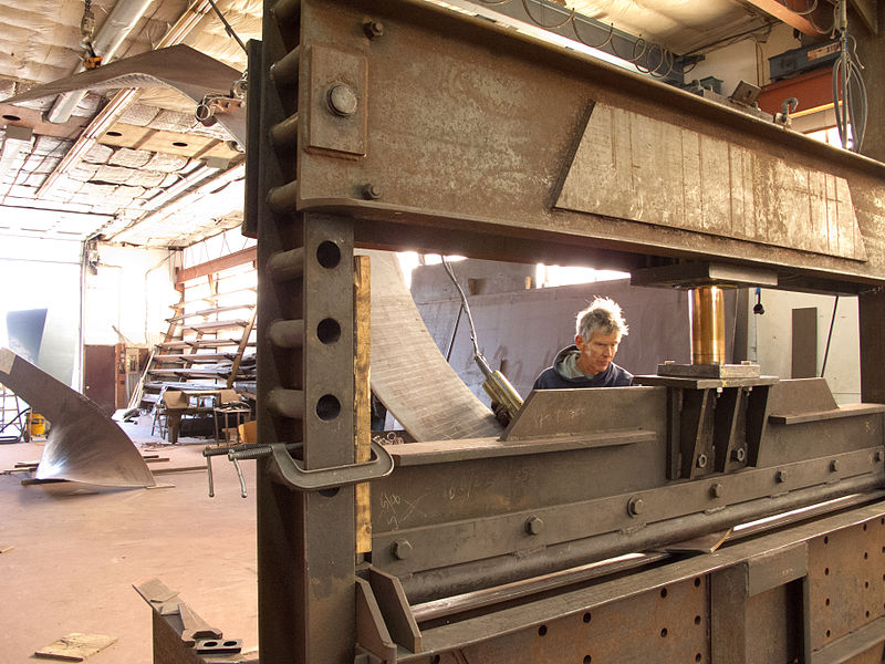
Hydraulic press is a complex unit used for metal bending and pressing. Almost every metal fabrication shop has one of this in their workshop because the hydraulic press is much efficient in its job, which is to bend press sheet metals.
Whether it stainless steel fabrication, aluminium fabrication or steel fabrication, a hydraulic press can bend press any type of sheet metal with precision until somehow the press is compromised.
But in some cases, the compromised hydraulic press can be repaired and used further and in some cases, you will need a completely new hydraulic press to maintain your workflow.
Anyway, how would you know when to move on to a new hydraulic press and when to give it another try?
That’s why I’m here today. I’m going to set the parameter by which you’ll be able to identify the condition of your hydraulic press.
Something wrong with the Hydraulic Press or not?
First of all, when do you know that there’s something wrong with the press brake?
When the press stops coming down to the repeatable depth or when the electrical system keeps shorting out, you should be prepared to do what’s necessary. Maybe repair it or change them completely. Sometimes fluid leaking from its power unit is an indication of malfunction. In this case, your customers won’t take the delivered product because it will have the stain of the machine’s fluid. But it’s a rare case scenario.
Judge by the number
If you are confused whether to replace the hydraulic press or not, then the first thing you should do is look at the numbers.
If only one of the unit or section of your entire machine is malfunctioning, you can simply replace the particular part, which will save a great deal of money than you’d have spent on a new machine.
You should also consider the auxiliary cost of buying a new one, freight rigging, setup etc. So if the problem is with one part of your hydraulic press, maybe it’s not the time to replace the entire unit.
Mechanical Health
Mechanical health indicates to the physical structure of the hydraulic press. This means you’ll have to check for cracks in the structure, amount of clearance in the grinding system among other things.
If you find any crack, it’s time for you to completely replace the unit because this one won’t keep its integrity anyway. So why waste money on upgrading it. Simply replace it.
Hydraulic health
Leaking of oil and lack of depth repeatability is what hydraulic malfunction covers. Besides, dirt and debris getting into the press then blocking the valves is also a recurring problem of the hydraulic press.
For most cases, this type of problems is easily solved by upgrading the respective unit in the machine. There’s no need to replace the entire press for oil leak because it can easily be fixed. But if you want optimal work speed and don’t have any problem spending few grand, you can always get a new one.
Other minor problems
Your press brake may need minor tweaks here and there. These are so minor that upgrading the unit completely is simply a waste of your money, like an electrical malfunction. Electrical problems can be tweaked very easily. You’ll only need a good pair of hand and eye to get it fixed. No need to replace the unit.
Conclusion: Whether it is laser cutting machine, metal rolling machine or metal bending machine, they need to be monitored regularly before thinking of replacing or worse, scrapping it completely. This way, metal fabricators can save the unnecessary cost of buying new machine for no good reason.

