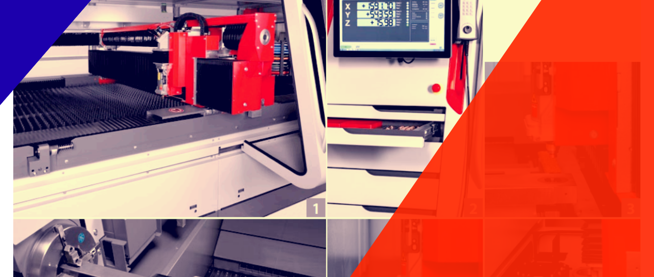
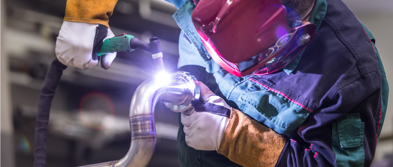
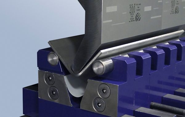
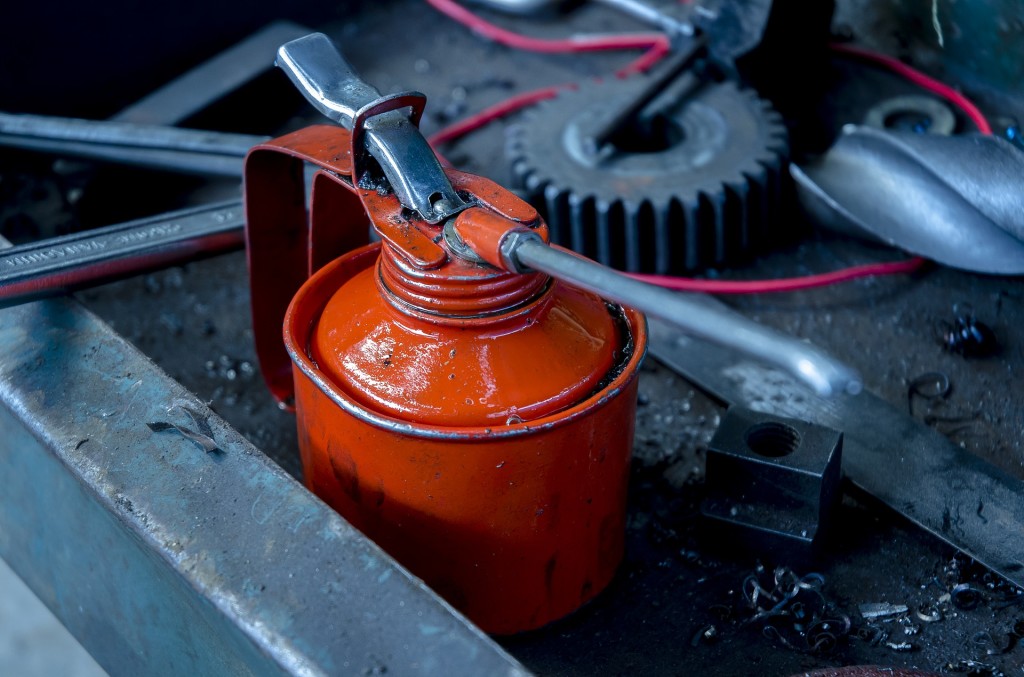
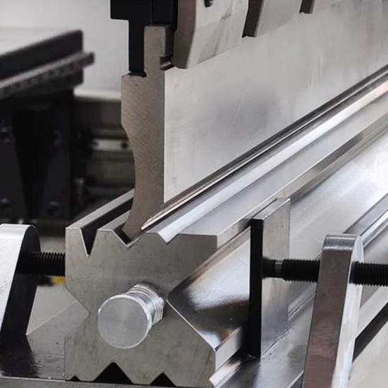
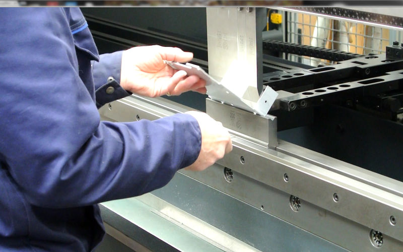
Being the Engineering Manager on a metal fabrication shop, I have seen laser cutting machine operators forgetting to set up the parameters, welders to use wrong weld pool, metal rolling and metal bending press brake operators not setting up the machine or not troubleshooting properly.
These small mistakes cost a lot. Such insignificant carelessness and we could end up with a batch of waste parts and product. No metal fabrication shop will afford to do the same mistake again once they see how much loss of time, effort, and material they have to carry. Thankfully our current team of workers and operators have gone through a lot of training to get past the position where a slip of mind will cost the shop a fortune.
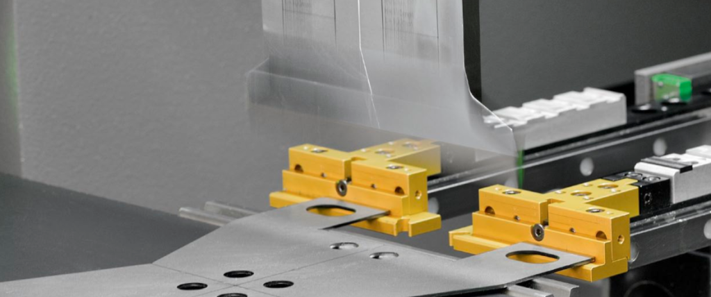
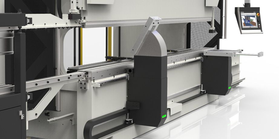
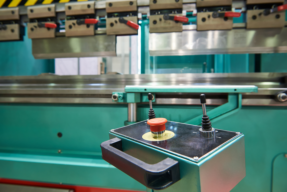
However, this can’t be said for all the metal fabrication Singapore shops I know. That’s why, I decided to talk about the common mistakes in metal bending Press Brakes (regardless of the machine, hydraulic or manual) and how to prevent them.
Untidy Press Brake Unit
The most common mistake that metal bending press brake operators make is leaving it unclean. The dirt and debris sit on it and eventually it causes excessive wear to the gibs.
To avoid the excessive wear and tear, the machine and its parts should be wiped regularly.
Lack of Proper Lubrication
Every moving part in the metal fabrication shop should be lubricated properly so that the movements are not restricted in any way.
There are many parts of a metal bending press brake which needs lubrication for the unit to work properly, especially the ram gibs. However, there are some units that have nonlubricated gibways. Again, there are some with grease fitting and automatic or manual oiling system.
If you have a traditional one which requires lubrication, forgetting to do so can lead to a workpiece disaster.
Upset Ram
Sometimes, when the bending load is much concentrated and as a result, the ram and/or bed over-deflects, they can take on a fixed/permanent upset in the machine’s center.
When the Ram or bed upsets, you will notice an angle, a large one, on the center of longer parts instead of the ends.
To fix the situation, the ram and/or bed should be remachined correctly. To prevent this from happening again, place the bending load carefully. Also, use only the sufficient tonnage.
Excess Gib Clearance
The clearance for gibs are different for each machine. Some manufacturers recommend 0.001 – 0.002 and some even higher, like 0.006 – 0.008 inch.
Too much clearance will lead to floating ram and too little will cause gibs to hold the ram as brakes. That’s why the clearance should be within the manufacturer’s suggested range.
Uneven Machine Levels
Ram gibs should be parallel otherwise the ram won’t work with a twisted movement. Make sure to ensure the leveling is perfect before you proceed.
Conclusion
Avoiding or preventing these problems will benefit the aluminium fabrication, steel fabrication, and stainless steel fabrication process and the metal fabrication shop in general. So, be careful and if possible, organize a training session for your workers & operators and make them more skilled or capable of handling the machine or the problems.
Cutting is a significant part of any manufacturing process. Starting from cooking to building rockets, everything needs little tweaks or cuts and different industries use different equipment to cut and prepare the final product.
In metal fabrication, there are a number of ways to cut a sheet metal and give it a shape. Plasma cutting, laser cutting, etc. are the more advanced ones. There are other less-complex ways to cut sheet metal within other machines like stamp die machine, metal bending press brake, etc.
Like any other process like welding, metal rolling, it is important that the operators take good care of the cutting equipment and parts to ensure best results, especially for stamping.
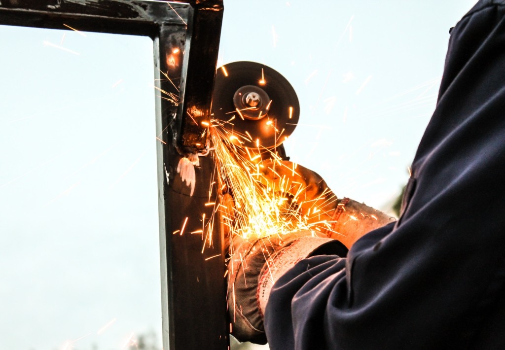
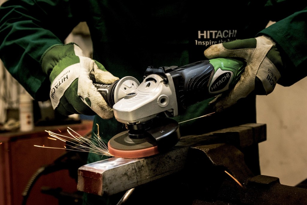
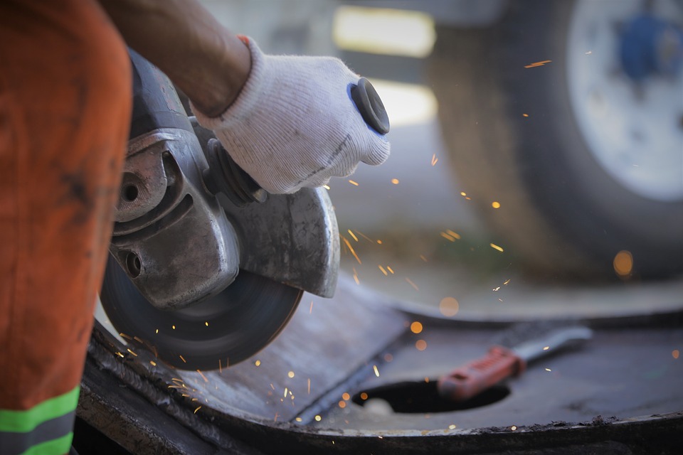
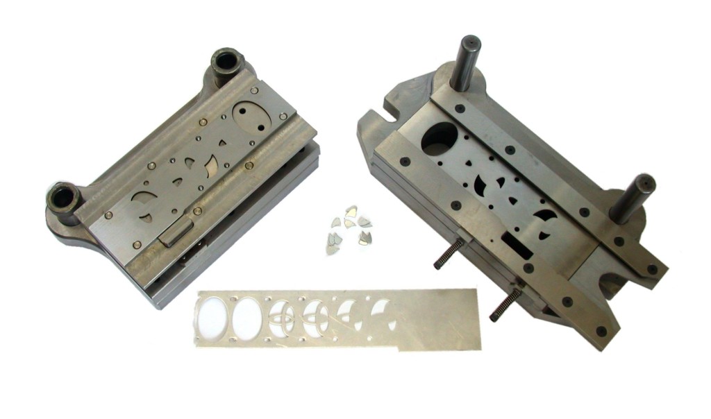
There are several cutting edges integrated into parts like punches, die steels, matrixes for stamping. It is important that the edges are maintained properly otherwise the resultant products will not be precise. The top edges of the die plate and other parts can easily be sharpened by grinding.
Grinding
The main issue with grinding is people can’t tell how much material should they remove in order to get the working edge.
In simple words, keep removing the material until all the wear and tear affected area vanishes. Also, remember that a matrix wears slower than a punch. So, you better be careful with the amount of material you are removing from different components and edges.
Treating the surface with chemical compounds
Surface treatment is used for matrix and punch components where the edges are worked with chemical compounds like titanium carbonitride, titanium nitride, and nitride.
Even though the question of how much material should be removed still remains with surface treatment, it requires much less material removal to get the sharp edge compared to grinding.
Sharpening the ejector pins
The punches that have ejector pins require additional attention while sharpening.
There are two different ways you can sharp the punches with ejector pins. One way to do this is removing the pins from punches. Then these two parts can be grinded separately.
However, the best way to do is to ensure proper pin extension while sharpening is by inserting a keeper key through the side vent hole that’ll retain the ejector pin while grinding.
Eliminating damage
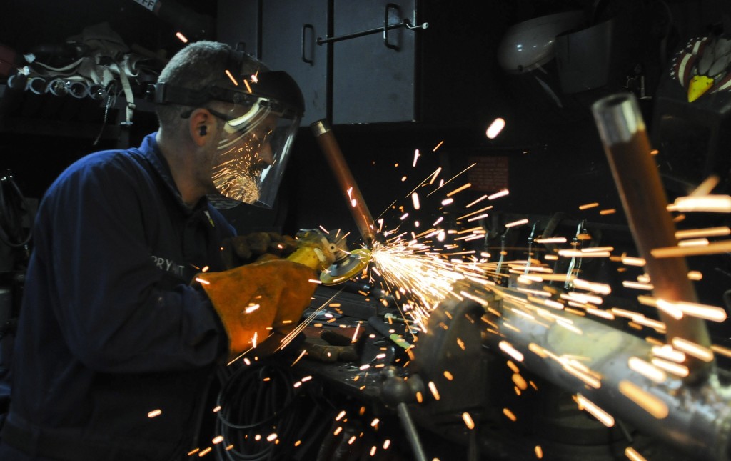
Damage caused by extreme heat buildup is a common issue with sharpening. That’s why it is important to take precautions to provide a smoother cutting edge. The heat can damage the water-resistant outer surface treatments.
These precautions might need some additional time. If the generated heat is too much, the tool life will decrease.
In order to understand how to prevent excessive heat and other damage, one must know how the damage occurs and how do they affect the sharpening process.
Whether it is aluminium fabrication, stainless steel fabrication, or steel fabrication, the damage caused by heat while sharpening the edges can make a big impact on the overall lifespan of the sharp edges. That’s why it is important that the components used in stamping are well-edged from the beginning of the process to the end.
Operating a tube mill comes with a lot of challenges. The operators and the managers both need to know how this problems and challenges come to play and how to solve the problems for the tube mill’s manufacturing process or what should be done to prevent it from happening again. If these problems are not addressed properly, aluminium fabrication, steel fabrication, or stainless steel fabrication processes won’t have precise tubes and pipes to work with.
Among all the problems and challenges I’m refereeing to, strip rolling and tube marking in the breakdown section are the two most common obstacles between the operators and their expected precise and productive tube mill production.
Strip Rolling
Inside the breakdown section, there can a lot happening that you don’t know. To give you a basic understanding of how the problem came to be, you can check for the following issues.
a) Misaligned or Uncentered strips entering the tube mill
b) Loose entrance table
c) Misaligned or Unparallel breakdown stand
d) Loose side box
e) Extreme wearing on the rolls
f) Incompatible design for the heavier than usual or lighter than usual gauges
g) Misaligned or Improper setting of side rolls
h) Camber from slits
i) No tie bars on side rolls’ passes
These are the main reasons for strip rolling in the Tube Mill’s breakdown section and among them, misaligned components are the most common ones. The operators must know that they can’t get the expected results if the machine setup is not done correctly because like any manufacturing process or laser cutting, metal bending, plasma cutting, metal rolling, and other metal fabrication processes, misalignment can cause issues to the overall process and even halt the production.
Tube Marking
Tube marking is another common phenomenon that tube mills operators see every now and then, especially when the machines are not calibrated properly. Apart from that, there are other accidents or malfunctions that can happen inside the breakdown section like:
a) Inappropriate strip width
b) Incorrect adjustment to the driven rolls to the gauge
c) Misaligned or Uncentered strips entering the tube mill
d) Unendangered driven rolls with the side rolls
e) Loose Driven stand
f) Misaligned or Unparallel driven rolls
g) Loose side rolls
h) Extreme wearing on the rolls
i) Incompatible design for the heavier than usual or lighter than usual gauges
j) Misaligned or Improper setting of side rolls
k) Camber from slits
l) Misaligned or Improper setting of driven rolls to the metal line
m) Uncoordinated drive RPM
Like strip rolling, misaligned components are the most annoying things that cause tube marking.
Also, tube marking can occur in the weld box or fin section and the primary reasons for that are:
a) Unnecessarily wide strip
b) Tight adjustment of the drive rolls
c) Misaligned or Unparallel driven rolls
d) Loose driven stand
e) Uncoordinated Drive RPM
f) Loose side roll box
g) Worn out fin blade
h) Wide side roll settings
i) Misaligned or Uncentered slide rolls with the driven rolls
j) Incorrect forming
k) Tight weld rolls settings
l) Extreme wearing on the rolls
m) Improper tube size between the slide roll and driven roll pass
So these are the main reasons for Strip Rolling and Tube marking in breakdown section which directly affects the materials (tubes/pipes) – soon to be used in metal fabrication shops.
Even though the operators are skilled and trained to operate in tube mills, there are still some challenges and issues that they need to face every day. Tube mill owners should arrange training sessions on how to troubleshoot the problem and figure out what was causing the problem. If these problems are not addressed properly, aluminium fabrication, steel fabrication, or stainless steel fabrication processes won’t have precise tubes and pipes to work with.
Today’s let’s explain some of the most frequent issues you face and the causes behind it.
Lost Mill Time
There can be a number of causes for excessive downtime for a normal operation or job or tooling. The main cause behind it is the absence of written procedure on the setup. This written procedure can help operators to control the overall process and even help with troubleshooting at times. That’s why not having one written can be a big issue especially the only variable of the mill setup equation is the manual control factor.
Secondly, having no setup chart can also be an issue as the tooling should be done as the way it was meant to. So, having no setup chart will only cost a lot of valuable setup time.
Sometimes even the lack of any formal training can be an obstacle to minimize setup and execution time. This is true for all manufacturing as well as metal fabrication processes.
Other reasons behind the loss of mill time are a disregard of all the parameters from the previous setup, poor mill condition, misalignment, poor tooling condition, etc.
Weld Zone Split
Too narrow strips with inadequate material to forge is one of the main reasons for weld zone splitting. Also, like any manufacturing process or laser cutting, plasma cutting, metal bending, metal rolling, and other metal fabrication processes, misalignment can cause issues to the overall process.
Poor split’s edge, improper fin passes, non-parallel edges, strip’s off-center approaches, improper chemical steel compound are the other few reasons for weld zone split.
Irregular Size
In the sizing section, there will be times when you’ll see irregular sizes occurring which is mostly due to the improper setup of the welding section, fin, etc. Also, if the forming part of the machine sends improper formed/sized tubes, irregular sizes may be the result.
Apart from that, the bent in the shaft or the oversized holes in the tooling can be the culprit for irregular size. To be honest, there are literally hundreds of reasons why the resultant product can have unusual sizes but it’s not possible to name all of them here. But if any of the reason above doesn’t fit as the reason behind irregular sizes, try checking the driven shaft’s ODs or ensure (1) the weld size is in accordance with your setup chart, (2) round weld size, (3) smooth weld scarf, (4) parallel side rolls, (5) proper cooling of the tube, (6) parallel strip edges, (7) tight bearing, (8) properly installed rework shims, etc.
Weld Chatter
Weld chatter is another common phenomenon that you see very often. The main reasons are insufficient weld bed or upset, inadequate weld power, dull knife or insert, faster weld cooling, a good distance between the weld box and scarf stand, etc.
Also, strip rolling and tube marking in the Breakdown section are another two most common challenges that operators need to face. But these two are their own thing and I’ll cover that in another article with detailed information.
Over the years, like laser cutting, welding, stamping, metal rolling, etc. metal fabricators have brought some noteworthy changes to the metal bending press brake’s design and the manufacturing.
In order to identify the most susceptible areas to stress consistent with sheet metal bending process in aluminium fabrication, steel fabrication or stainless steel fabrication, press brake frame components are developed and engineered to use the principals of mechanical engineering combined with the CAD Technology.
Additionally, many progressive manufacturers want to take the CNC machining tech to a position where the machine can meet productivity and reliability needs of a customer with every production.
With Antidefletion devices like an integrated dynamic crowning system or a crowning table, a good number of problems related to frame deflection is most certainly somewhat eliminated or reduced. Along with that, upper beam positioning (UBP) feedback devices like a pressure reference system, and a linear encoder, the metal bending press brakes used in metal fabrication shops can be very appealing.
Then adding precision metal bending press brake tooling & the multi-axis backgauging can give you the components for a sheet metal precision air-bending forming setup.
Perfect bend needs a lot more than a fancy spec sheet
If a press brake is well equipped to handle different variables which the machine builder can’t monitor or control, you can’t be sure that you’ll get the perfect bend and the variables won’t affect it in any way. So, don’t get fooled by the fancy specs sheet or over-designed catalogs of the press brakes if you are looking for precision and productivity for your metal fabrication shop.
Material is perhaps the most important variable in this case. These materials are not always the same. Some might have a better finishing than other and even different thickness as a matter of fact. Regardless of where the materials are sheared from, they will be delivered to the metal bending press brake along with their inherent differences in material thickness, grain structure or tensile strength.
The material variable can be a problem for the machine operator as he is only instructed to get the resultant product and not how to handle the variable. Well, they have to let the variable handling to the automation of today and figure out the impact and effect.
Angle measurement method
There has been some experiment and trials since the early 1950s where many builders have tried to combat the effect of this material variable.
The earlier attempts were futile as the numerical controlling unit were not able to withstand the real-time feedback issues. Additionally, the press brakes were servo-controlled, which is why they lacked precision repeatability.
But there had been several developments and now builders are able to incorporate adaptive control monitor that can measure the displacement and the force in actual time as the machine’s ram goes through a cycle. This is not the only thing that is changed recently, there were other advancements which helped the machine achieve higher precision and repeatability so that every time you get a sheet metal out of the process brake, you get a good piece with an almost perfect bend. However, there are still a lot of scopes for improvement.
Welding, metal bending, metal rolling, cutting – all of them aren’t limited with one single method. Metal fabrication shops are equipped with different methods and machines. For example, metal fabricators use plasma cutting, laser cutting, etc. for cutting.
Same goes for welding, metal bending, rolling, stamping, etc.
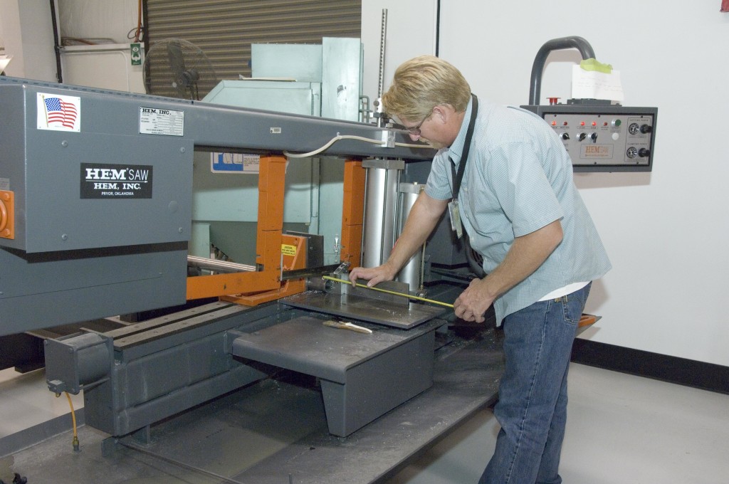
Similarly, the sawing equipment for pipe or tube also varies depending on the cutting needs. If you are going to saw the pipe or tube in substantial quantities, you’ll most probably want to use a cut-off saw. So, let’s talk about increase cut-off saw productivity and how to increase it.
Saw designs
The best saw for cutting through hollow pipes and tubes is designed with the goal that the sharp edge cuts the workpiece at a slight/minor angle. This is particularly vital when cutting settled square tubing stocks, which displays an extended surface on which the saw edge begins its cutting.
While sawing has started on the wide surfaces, as happens when the edge is parallel to the workpiece, the drive engine and cutting edge’s teeth are really stressed out as they pull a substantial chip load through the cut.
Fluid or Lubricant
For sawing any solid pipe or tube, most metal fabricators suggest using as much fluid as possible.
However, this might be a problem for hollow pipes and tubes as a good amount/volume of lubricant or fluid can go inside the several cavities and therefore collect there or simply drain out the pipes and tubes. This makes a big mess in your workplace.
Blade of the saw
Pipes, tubes, and structural pieces, for example, angle press and I beams don’t have the mass that solids actually have, so they will probably vibrate while they are being cut. Held in a saw’s tight clamp, the workpiece goes about as a tuning fork as a portion is being cut. To limit vibration and the going with a screech, exceptional multi-pitch saw blades have been produced.
Pitch is used to explain the tooth dispersing and is spoken to numerically as a number of teeth in each inch.
With the multi-pitch blade, the symphonious vibration as often as possible caused by a single-pitch blade is limited, and the screech that can happen is either diminished or wiped out in numerous occurrences.
Nesting
The most evident approach to amplify a saw’s utility, especially when the prerequisite is for a huge amount of short pieces, is to settle the stock so the saw is cutting numerous workpieces all the while. While settled expenses continue as before, this system can set aside extra cash since time isn’t lost sitting tight for the saw to reuse. Besides, factor costs for cutting fluid and blades don’t increment considerably when estimated against the number of pieces cut.
Conclusion: Whether it is aluminium fabrication, steel fabrication, or stainless steel fabrication, metal fabricators always look for ways to make the processes more and more productive for their use. Eventually, there will be something specific for such your need (huge amount, small pieces). But until that day comes, you’ll have to stick with old saw cutting for a while.
Achieving precise result with desired quality while maintaining a competitive cost is the reason for any innovation in any metal fabrication process like laser cutting, stamping, metal bending, welding, metal rolling, etc. Regardless of the material, aluminium fabrication, steel fabrication, or stainless steel fabrication processes are upgrading for the better.
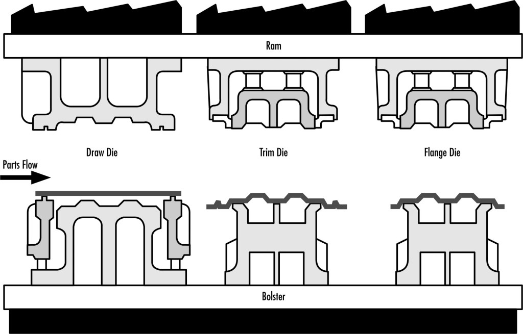
With the same goal in mind, deep drawing press techniques and the equipment used in die technology are being optimized to achieve a reproducible and productive forming process.
Sheet metal flow sheering
One of the main reasons for deep drawing irregular parts or components like automotive decklids or fenders is that the metal sheet flowing between the draw binders must be steered properly, resulting in no cracks or wrinkles.
In order to steer the metal sheet flow into the binder of your draw die, these methods can be helpful.
a) Draw beads: By causing friction and bending forces, draw beads can easily hinder metal flows in specific areas of the blank holder.
b) Lock Beads: These lock beads have the capability to stop sheet metal flows at any area of the binders.
c) Blank’s shape: The local increase of blank size can contribute to higher friction and forming forces, which hinders metal flow between the binders.
d) Friction between the binder and the blanks: The friction force can be altered in order to steer the metal flow between binders. Widening or narrowing the space between binder, altering the pressure between the binders & blank and spraying less or more lubricant on blank are the three typical methods to increase and decrease the frictions.
Hydraulic cushion system
There are two basic ways that deep drawing can be done. One, in a dual press that has two rams (blank holder ram and primary ram) and two, in a single press that has a cushion system on the press table. Both can be either hydraulic or mechanically driven.
A dual press or double-acting press is mostly used for deep drawing. On the other hand, a single press or some single-acting press have hydraulic cylinders in the 4 corners of its press table. Each of them has a unique servo valve to ensure the strokes of each of the cylinders can be run over by particular blank holder forces. This also helps the forming process to be more programmable and reproductive.
Die Stiffness and Flexibility
Usually, dies are made to be stiff, not flexible. But the material cannot be 100% rigid and they shouldn’t be 100% rigid.
While using a CNC multi-point cushion system, each of the cushion pins could be utilized at fullest to influence the corresponding defined region of the low binder surface. The action can be optimized with the SE-BH or segment-elastic blank holder, developed by the IFU at the University of Stuttgart.
This blank holder can be made from any nylon-based thermoplastic component and they are usually designed with a pyramid-shaped steel insert. This blank holder then force is then introduced to the inserts to ensure sound corresponding between the blank holder forces and the pressure-enabled base region of the insert pyramid.
From the functionality and actions, it is clear that the stiffness of the die or its flexibility has a lot to do with the deep drawing operations.
From laser cutting, metal bending, welding, stamping to metal rolling, everything in got a ton of upgrades in the metal fabrication & forming industry and stamping is no exception.
Whether it is for stainless steel fabrication, aluminium fabrication, or steel fabrication, stamping process has evolved over the last decades and it is clear that the upcoming years will be as eventful for stamping if not more.
However, to advance from the position we are in right now, we must be up-to-date about the advancement that affected metal forming or metal stamping in general.
Here are the outlines of top 5 improvements available to modern press-room operators.
The lubrication system
The Key to upkeep any mechanical unit related to metal stamping is lubrication. It is also the main cause of the stamping press downtime.
Today’s modern lubrication has successfully overcome all the failures of its ancestors in every way possible, including monitoring, accuracy, delivery, etc. The previous system heavily relied on the characteristics of gravity and the mechanics of a hand pump.
But the new lubrication systems are capable of delivering pressurized lubricants with the pumps, which is powered by motion, electricity or air. Besides, before the modern lubricant/oil crisis mentality, wasting or even thinking of wasting was not considered as people thought it will greatly affect the cost. At that time, people thought the more lubricant you supply, the better results you get. This is proven wrong for many reasons. First of all, this is wastage and also, this could lead to spillage and contamination. Thankfully, modern lubrication system addresses the issue and ensure the right lubrication flow into the machine.
Electric controls
Sweatshops days are gone. With them, the antique method of controlling stamping press machines is gone too. Today’s system offers an even complex option in an all-in-one compact package that not only made the process cost-efficient but also made it easier to attach to a press.
The options of integration of speed control, self-diagnostics, setup parameters, programmable functions for different press attachments, pneumatic system, and lubrication are available.
Variable-speed drive
Even though the addition of variable-speed drive is not new in metal forming, it is worth mentioning as it brought a revolution for the process in general.
These days, any press can be easily converted to a variable-speed drive from any other type of drives. This allows full torque at any particular speed.
Safety Equipment
In the early 20th century, safety was not a significant issue for press handling. Thankfully, the safety concerns are taken much seriously these days and the advancement in stamping presses have made safety equipment modification much easier.
The pressroom safety advances include the safety light curtains which the guard workers’ hands and fingers with the infrared barrier. If the infrared barriers are broken somehow, it sends a stop signal into the press controls immediately.
Temperature-Monitoring devices
It is true that lack of lubrication is one of the main reasons of press downtime. However, heat also has a major part to play in this case.
But the introduction of heat—sensing probes, detection devices, sensors have allowed simple machine control and monitoring which turned the table to an extent.
However, these aren’t the only upgrades we got over the years and we are sure that more to come very soon.
Troubleshooting the laser cutting, metal bending, welding, stamping or metal rolling machines is a crucial part of metal fabrication shop maintenance.
Maintenance and troubleshooting is an inseparable part of aluminium fabrication, steel fabrication or stainless steel fabrication. However, people think troubleshooting the stamping process is only the process of identifying and remaining damaged dies. But troubleshooting is beyond that.
Here’s how to do it:
Identifying the problem
Identifying the parts’ problem is basically the easy part of the whole troubleshooting process. This part of the process can include looking for cracking, splitting, wrinkling, excessive burns, understrained parts, nonconforming part geometry, score marks, slug depressions, and dents.
The unit who is responsible for checking the parts needs to have a sound understanding of the different types of failures. They’ll also have to know how to communicate with the unit responsible for the repair and explain to them what’s wrong.
Ensure the die is set up perfectly
Every now and then, stampers make some major changes to the die and then they find out that the die wasn’t set up properly.
Here are some things you can check for to ensure if it has been set up properly or not.
- First, verify the height of the die shut, press tonnage readings, and stop block lead readings. If by chance you are using the bottom makers, make sure that they are visible and to the proper depth in the scrap or the part.
- Ensure that the die is firm against the positive location stops. Also, ensure they are parallel to its coil.
- Make sure the method of applying the lubricants is correct for the application. The die and the metal should be lubricated properly to achieve precise results. The rollers and sprayers should also work properly.
- Look into the width, thickness and the metal mechanical properties of the coiled material.
- Verify the feed and pilot feed release timing on the progressive dies.
- Ensure the pitch or the feed distance is correctly set-up.
- Ensure that the pressure systems, for instance, the press cushions, nitrogen systems, and hydraulic pressure systems are charge and prepared for the right operating pressure.
- You need to make sure whether the dies are flushed with the ram and the bolster plate. They must not be any debris below the die shoes, plates, or casting.
- Double check all the remaining press parameters like the clutch pressure and the counterbalance.
- Check if all the gauges and locators are in their right positions or not. The blank should also be checked to see if it’s in the right position or not.
- There shouldn’t be any loose piece of slugs, scraps, or obstruction laying on the die.
- The coil material should be checked to verify the levels, straightness, and flatness before entering into the die. During the production, periodic adjustments to straightening the equipment may be necessary.
- Lastly, all the nut-bolts used to secure the die inside the press should be tight enough to avoid any accidents.
Whenever a high-density heat source, like a laser, applied to the surface of a metal workpiece, it is distorted. Now, being able to predict this distortion allows you to use the laser or high-density heat source, and direct it in a specific manner in order to shape and form the metal without the need using any stamping dies or another tooling. In the past, this not actually a feasible option as it required a lot of manual labor as well as skilled operators to perform the complex operation. But now that developments in neural networks and simulation software have advanced, it is possible to predict and determine the feasibility of such a process in the manufacturing workspace.
How it works
A laser beam is shot down on a specific part of the metal work-piece. Due to its metallic properties, that part of the metal surface will have to expand. However, due to the presence of the cooler metal surrounding it the metal cannot expand to its sides and thus has to extend outwards, away from the surface. Once that portion that has been deformed cools, the stress from shrinking permanently deforms it. This process is then repeated across the surface following a predetermined design specification in order to create the shape required by the manufacturer.
This process has been done before in the industry, however, only in necessary edge cases like forming the large and heavy steel plates for this and also for straightening out steel beams. This technique has also been used to remove the distortion produced from welds during fabrication. The process has been used sparingly due to the complexity behind it and the extensive man-hours required to execute a job properly.
Making it better
The FLAIR project has revolutionized laser thermal forming and made it feasible for more widespread applications. The project is very smart in the sense that it uses DPSs (high-speed digital signal processors) for controlling the intelligence behind it. Using these, it is able to convert computer-aided design models into parts with limited human intervention. In essence, the project works by processing the 3D model and then the neural network determines how the laser should go about forming the actual part. This removes the need for human expertise and intensive labor to work things out. Some of the parts made from this process are either too difficult or almost impossible to create using standard metal bending techniques.
Visualizing it
When you add in some graphics to the whole project, you are able to accurately monitor and track the whole process. The neural network is smart enough to not only process the required motion for the laser machinery but also the real-time properties of the metal and the changes it goes through due to the contraction and expansion during the forming process.
Conclusion
Being able to predict and automate processes like this can be expanded into other manufacturing processes in the metal fabrication industry, like laser cutting and metal rolling and could help stainless steel fabrication, aluminium fabrication, and steel fabrication thrive.


