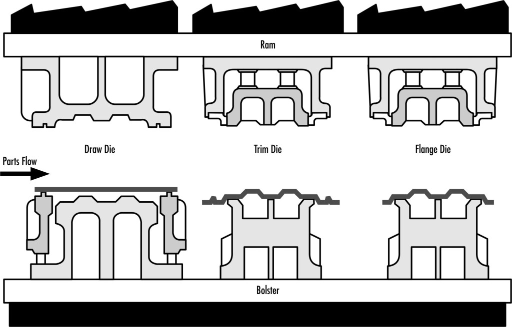
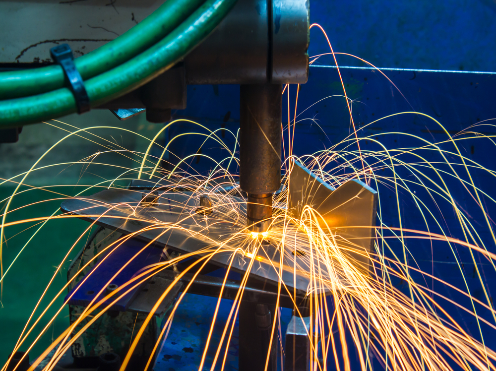
We all know how a single bad decision can ruin the entire laser cutting, metal bending, welding, or metal rolling process. One bad selection of tools and parameter or just one bad decision is enough for the entire production line to be a disater. It is true for stamping too.
Whether it is stainless steel fabrication, aluminium fabrication, or steel fabrication, a bad selection of feed can ruin the work for you. But that’s why we are here.
Raw Material feed comes in 3 different styles:
- Servo-driven
2. Air-driven and
3. Mechanical
These three have different suitability in metal fabrication stamping. However, if the situation is like “one feed suits all” then, I would suggest servo feed, which I’ll talk about later. First, you need to know about air feeds and mechanical feeds.
Air Feeds
Among Air feed, Servo feed and Mechanical feed, these are the most cost-effective ones. They are reliable too.
However, they are not as precise as mechanical or servo feeds. Even though sometimes the stamping tool pilots are capable enough to make up for the little variations in the feed length. It usually happens when the force applied to pull the coil stock is different due to changing condition for controlling loops at its infeed.
Another major issue with air feeds is the timing. As they are air driven, there is some inherent lag, which you cannot do anything to prevent.
Mechanical feeds
Mechanical feeds are the most accurate, precise and fastest feeds that we have ever used. They are can run over 2000 SPM in the right conditions. But our number one pick for regular and all situation use is Servo feeds. Why?
Servo Feeds
Servo feeds can be expensive than both mechanical and air feeds, depending on the model. However, they are much more versatile and capable of handling a variety of stock widths and thicknesses.
Besides, they can be programmed for individual jobs, which is why you don’t need to set up the feed on the changeover. You just need to pull on the programs and pitch-length of coil stock, which is fed on each press cycles.
Some of the servo feed models can store up to 200 unique programs. These Servo feeds likewise are moderately quick. Obviously, speed is an element of the pitch setting: the more extended the pitch, the additional time you have to sustain, which influences the press speed. All things being equal, for speeds up to 650 or even 780 strokes for every moment (SPM) on short pitches, they can carry out the activity exceptionally well.
With servo feeds you get a for all intents and purposes interminably customizable feed cycle. So for example, in the event that you are doing in-die tapping and the strip is allowed to move just for 90° of the press cycle, you can program this on your servo feed. It’ll influence the speed to some degree since you need to sustain your pitch in a shorter time span, yet by a similar token, on the off chance that you can utilize 220° of the press cycle, you have a more drawn out time to nourish your crude material and can run even faster.
Additive manufacturing has been in the experimental phase for the last two decades. It was used in Aerospace, Medical Equipment production and many other sectors for a trial run. Now that it has proved its worth, it’s becoming more and more popular in several manufacturing industries like metal fabrication.
Now the use of Additive Manufacturing (AM) has reached to every corner of metal fabrication but there is still time before AM takes over laser cutting, metal bending, welding, metal rolling machines, etc. Once the availability of this technology increases, there won’t anything to stop it from dominating stainless steel fabrication, aluminium fabrication and steel fabrication processes.
What is the state of Additive Manufacturing today in Metal Fabrication?
It’s not a secret that there is a lot to be done before AM technology can fully become accessible for metal fabrication shops. Right now, engineers are taking careful steps in finding the sweet spots that will link AM to the regular metal fabrication processes.
Machine manufacturing companies are working on compatible equipment design and production that’ll ensure consistency and repeatability for the result. If a metal fabrication shop is going to use AM for producing a part, they need to make sure every part that comes from the machine are completely identical to the other ones. So, to increase repeatability, engineers and designer are working together on AM technology and at this rate, we would reach our goal sooner than later.
Topology Optimization on the AM Design
Topology optimization means identifying the least amount of material for a specific design and few boundary conditions. For a very long time, Topology optimization has been known to be a fun little exercise for mathematicians. However, people related to manufacturing industries also made some effort to implement topology optimization in practical life, not in papers. But the biggest problem for this was manufacturers didn’t have any proper equipment to produce the output because many of the algorithms would suggest organic looking geometries that couldn’t be possible to make with traditional machines.
However, the introduction of Additive Manufacturing to the Topology optimization has made it possible to produce those un-producible parts that topology algorithm suggests.
Material for Additive Manufacturing
Many believe virgin materials to be the best choice to get the part you need. Also, disposing of the unfused powder is not at all economical. Besides, there is the risk of increasing carbon footprints.
Now, many companies are working to figure out how they can recycle, recondition, repurpose the leftover powder in the best possible way. For instance, a company division that does not have strict prerequisites for its noncritical parts and components may have the capacity to utilize the unfused powder from the company or industry with stricter components or parts qualification requirements.
Will it have any Impact on the supply chain?
Yes, it will.
The biggest impact will be on the parts that need several components and joining. These parts will now be produced at a single machine where it needs several components from several workstations now. So, time, complication, cost, all will be decreased and the supply chain will be more efficient.
Automation has begun to impact the metal fabrication industry, which includes stainless steel fabrication, aluminium fabrication, and steel fabrication. This tends to have a negative impact on workers as proved by a study that showed that most people think that they are at a risk of losing their jobs to automation. This is apparent when a lot of industrial processes, including metal bending and metal rolling, are being automated. Despite all this, the end goal should be a positive one where workers can coexist with robots and be productive.
Welding Expertise
An industry needs people who know about the job and are experts in it, no amount of automation can overcome raw experience. Employing a programmer to develop a system for the robot to weld is easy, however, dealing with welding problems or knowing about welds is a major detriment. This is where expert welders come in. They can tackle problems based on what they already know. Hence it is more optimal to train good welders in operating these robots as they are familiar with all the related intricacies of welding properly and correcting errors.
Bridging a Gap
It is of no surprise that traditional workers will not exactly welcome automation and manage robots to their job properly. However, some of the problems of traditional practices detrimental to the industry can be minimized and at the same time, the disparity between workers and the robots can be reduced by engaging the workforce with automation. Firstly, it is important to understand which shops, depending on the parts, will benefit from automation. For example, in the case of laser cutting and pressing brakes, a robot can carry out these tasks with great precision repeatedly. Therefore making it an ideal candidate for automating. However, in the case of an old plasma system, using a welding robot is not ideal. Secondly, a healthier work ethic can be promoted where, instead of trying to meet the bottom line and creating the bare minimum number of welds, welders can be encouraged to be more productive and treat the bare minimum as a beginning instead of the end goal. This is a mindset that cannot be changed by automation alone, and so encouraging welders to be more productive is a good decision. And finally, employing welders that have an interest in robotics and then training them to develop and maintain the welding system will be greatly beneficial as the robots will run on programs created by experienced welders.
Proper Communication and Garnering Interest
The worries about workers losing their jobs to automation can be mitigated by companies being more vocal about their intention. Automation is there to aid the workers, not replace them. Moreover, due to rising demands, automation is required to meet those demands. Therefore it is important to nurture welders who will learn to take care of the robots in the long run instead of despising them and will help make welding more reliable and productive.
Different fabricators of the metal fabrication industry have their own type of heavy-duty racking. These range from stainless steel fabrication and aluminium fabrication to steel fabrication. Therefore, racking systems must be designed to fit the needs of all different fabricators and be sturdy enough to not become a workplace hazard. To accomplish this, some design elements must be employed when making the racking system. Five important ones are highlighted below.
The material of the Rack itself
The type of steel used in the making the columns, arms, and shelf beams of the racking system and their respective designs dictate the system’s performance. In order to handle high loads, hot-rolled I-beams are enough. Wide-flange or standard-shape I-beams are also enough for the task of holding up the heavy loads. As an added benefit, these types of steel are also very resistant to damage from other handling equipment.
Another challenge for racking systems is deflection when materials are loaded unloaded. Due to which the shelf deflects while loaded and reverts back when unloaded. For most racks, this can be thousands of times over the life of the rack. This is where lower grade steels will start to show permanent deformation. Therefore, choosing higher rated steels, like 50-KSI steel is optimal, as they resist deformation and retain their shapes even after numerous loading and unloading cycles.
These steels are produced from processes such as laser cutting, metal bending, and metal rolling.
Durable Hardware
Strong connections between the arms, beams, and columns are required to hold a substantial racking system together. The importance is magnified in the case of cantilever rack systems, where the support consists only of a single central column at one end of the arm.
Ability to Hold 100% Load
Racks should be designed keeping in mind that the rack will be used at 100 percent capacity and all arms will be loaded simultaneously. For this reason, the columns and base of the rack must also be designed to sustain the full load. Moreover, in the case of cantilevers, special care must be taken to ensure the rack is designed to be stable even when it is only loaded at one end.
Even Load Bearing
Materials and items to be loaded on the rack vary greatly in terms of size and shape. While some longer or larger items can span the length of the rack other heavier items might rest elsewhere. This makes for unevenly balanced loads. In such cases, it is important to design a rack that is capable of sustaining full load no matter where it is located on the rack. Unless racks are designed in this way, heavier loads placed on unsupported parts of the rack will deform it and compromise the rack’s integrity.
Proper Welding
Racks are prone to damage and show structural weaknesses if not welded properly. Therefore, arms and connecting beams should be fully welded and any signs of poor welding should be dealt with as this is a serious threat to both products and employees alike.
When talking about environmental friendly manufacturing, green tools or energy-efficient ones rarely come to mind. However, machine tools are made up of motors and various complementary components which tend to consume a lot of power when operated. Recently, the move towards green has bled into manufacturing. Therefore, a new set of standards put in place by the International Organization for Standardization (ISO) can help measure, reassess and redesign machine tools to improve performance.
Machine tools are heavy industrial level devices that rely on a large amount of power to perform tasks such as laser cutting, metal bending, and metal rolling. These processes involve the use of various different tools which make up a sizeable proportion of the energy costs. Moreover, cooling and lubricating systems during metal fabrication processes add to the total energy consumption.
Calculating the ecological footprint of machine tools is not an easy task. More often than not, investing in new designs comes with a lot of forethought as these tools are affected by multiple variables, including, economic value, the technical specifications of the tool itself and finally operating requirements.
ISO has published parts of the new international standards, which encourages the analysis of machine tools based on their functions and to highlight similarities between tools that are reasonably different from each other and there are different variations of the same tool type.
The Standards That Are Paving the Way for the Future Machine Tools
ISO 14955-1: Part 1 of the Environmental evaluation of machine tools, deals with the efficiency of the tools during their operational lifetime. The tools are evaluated based on the components they are made up of, the functions the tools carry out and the associated energy demands. These are then compared and evaluated against both older versions of the tools and newer technologies for further improvement and redesign.
ISO 14955-2: Part 2 of the Environmental evaluation of machine tools provides practical methods for measuring the energy supplied to machine tools and their different components as specified by ISO 14955-1.
Ralf Reines, a convener on behalf of the ISO technical committee in charge of developing these standards, has stated that these standards are the only ones in existence and that they provide an extensive methodology that can be applied to all machine tools, no matter how diverse the tools are. This means that, even though machine tools used the fabrication of different materials, such as stainless steel fabrication, aluminium fabrication, and steel fabrication, the standard can be applied to all of them. The goal of setting these standards is to design and use more environmentally friendly equipment without compromising on performance.
A Greener Future
The machine tool production industry is a multi-billion dollar industry and as the demand for more energy-efficient machines is on the rise, designers will have to abide by these new set of standards to produce the next generation of machine tools leave a smaller environmental impact and be more energy efficient.
Inventions come from experiments. If you don’t try things that people never tried because they just don’t make sense, how will you become more than an ordinary metal fabrication shop owner?
Laser cutting machine and metal rolling machine, doesn’t go well with each other, right? There’s nothing common. But laser cutting and plasma cutting machines have similarities like metal bending press brake and metal rolling machines. That’s why hydraulic presses are being used in roll forming applications these days. But how did it happen? Somebody tried. That’s how it happened.
Even though not all of us are using hydraulic press brake in roll forming but there are quite a few who take interest on the idea. But what makes a hydraulic press brake suitable and preferable for roll forming application.
More Efficient
Whether it is stainless steel fabrication, aluminium fabrication, or steel fabrication, every metal fabricator wants to finish their products faster.
Director of marketing and sales at Beckwook Press Co. Mr. Josh Dixon said that the desire to leverage hydraulic press brake’s versatility while the speed is increasing – becoming more prevalent with most manufacturers. He also added that many clients focus on the quicker approach so that they could have a long stroke as well as allow the operator or robot to access the working areas for unloading and loading.
He continued that with Dahlstorm’s coil-applications, they just needed a small stroke which is why it was a bit different. They have been successful in accomplishing this with the custom-made hydraulic circuit, which was designed to let the short cycling of that press, at the same time preventing its ram from any overshooting that programmed retract and extend positions.
He added that it’s easy to achieve speed through separate power packs and they fire up the hydraulic fluid to produce the speed within the short strokes.
As it is a hydraulic press, the Dahlstrom Roll Form isn’t sacrificing any power even with those short strokes. Full tonnage of a hydraulic press could be delivered at any particular point within the stroke. It’s even possible for the point the press hits the part.
Extended Die Life
Most roll forming clients have their tooling for the works performed at the Dahlstrom Roll Form. Anything that should be possible to ensure that venture and increase its life likely would be incredibly appreciable.
Since the hydraulic press’ stroke can be controlled to modify speed anyplace amid the whole stroke, the controls can slow down its ram as it is going to experience the metal for punching. This is done to limit shock, which brings about more steady wears on the die.
Flexibility
Generally, a hydraulic press brake can apply the pressure all over the tonnage range. That’s why it is capable of doing different types of jobs.
Roll forming actually is a ballet of different actions — uncoiling, stopping, feeding, indexing, and punching — happening at the same time. There are likewise pneumatic gags on the instrument that powers on and off as various parts of the strip are punching at multiple stages. At the point when things cooperate as they are customized to do, it makes fabricating less stressing.
What if the laser head, power source, nozzle and other parts of your laser cutting machine didn’t work together? It won’t run, right?
Whether it is a laser cutting machine, metal bending press brake or a metal rolling machine – they won’t work until all their components are working at sync. Same goes for a metal fabrication shop.
The success of stainless steel fabrication, aluminium fabrication, or steel fabrication don’t depend on how expensive your machines are or how experienced each of your employees are, until they work as a team, your results will be “okay”, not “great”.
Yes, your teams do need the right tools and equipment to work with. However, if your team is dysfunctional as they don’t match in their working style, things will be complicated even with top-notch machinery at their disposal. This is clearly not a characteristic of an ideal team. Then what is?
An ideal team for a metal fabrication shop will be the one whose members complement each other’s skills and working style. I like to separate a fabrication process into 4 different parts.
- The design and instruction
2. Execution of the design
3. Evaluation of the product
4. Packaging and Delivery
For example, say Bruce is the creative engineer for your fabrication shop. His work is to design and develop the basic layout of a product. Then there is Clark who is responsible for all types of machine works. Let Victor be your quality assurance guy who excels in details and knows what’s wrong with your production. And lastly, you’ll need a packaging and delivery manager who is Barry.
Here, Bruce is the team leader of your crew with the quality of directing the regular workflow. For quality maintenance, Victor is there with his analysis and evaluation skills. Clark and Barry have their own sectors that require fabricating, packaging and delivering the products, which is the core of a shop. See how balanced this team is?
An Ideal team should be just that. There needs to be a group of people or a specific individual to sort the work out for other employees and plan everything. Then your shop needs a group of experienced and skilled operators who will listen to your product designer and follow his instruction to deliver what’s needed. Once the product is finished and brought down from the machine, it should go to the quality assurance department where the work of your operators will be checked. Lastly, when the products get a green signal from the evaluation team, it goes to the packaging section where it is prepared for delivery. This is how a team in a metal fabrication shop should work.
When they work together and sync with each other’s work style and preferences, the final product turns out to be better than what you’ve expected. For that, it’s important that they understand each other’s works and why their own work is import to the person in next and vice versa.
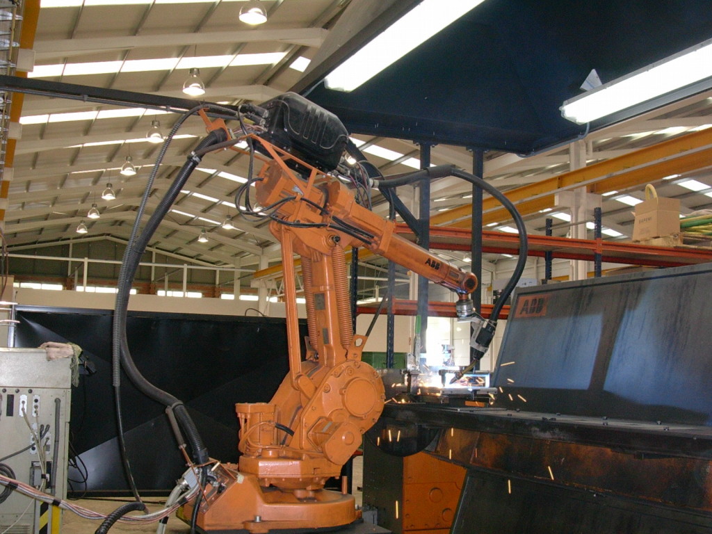
Automation is a major part of today’s metal fabrication shops and we are happy that we have these robots by our side because the number of injuries has fallen since they took the moving and risky parts on their hands. However, this wasn’t the case when automation was first introduced in stainless steel fabrication, aluminium fabrication, and steel fabrication a few years ago. People thought that automation in laser cutting, metal bending, metal rolling, welding, etc. will decrease their value in the fabrication shop. Somehow, people are still scared of losing their job, according to a study by Ball State which was published in the popular Journal of Social Sciences & Medicine. Even though some people are optimistic that automation won’t make any change to the operator’s value, we can’t deny how the culture in metal fabrication shops has changed due to automation in almost every process, especially in welding.
The change in shop’s culture has made welding operators scared of the robots involved in their work and the study by Ball State named the fear of the operators to lose their job as “automation risk”. Even though manual knowledge is an expertise in some aspects, in some places, robots are best suited which you can’t deny. I’m talking about complex robotic welding.
Good Communication
Today, welding operators are not threatened by automation as they once were. But it’s not enough. Metal Fabricators need to mitigate their worries. One way to do so – is good communication.
By communicating and committing, things can be more relaxing for the operators as Mr. Cedric Moore explains, the plant president at Glendale Mfg. Co.
He added they were straightforward about this with their workers. They thought about the well-being of their employees and they also assured that none of their employees will lose their job over the new automation help in welding.
If other fabrication shop owners can talk to their employees directly about the matter, they might feel better about sharing their workstation with a robot.
Manual Expertise of Welders
Besides, the robots in welding don’t work like a plug-and-play music player. They need constant monitoring or observation by an experienced operator. That’s why metal fabrication shop owners can’t just rely on their robots to get their order done. They need the skilled welders to guide its programming.
Welders should know to weld
No matter how well a person knows robots and its mechanics, he wouldn’t be able to keep up with client’s expectations unless he has years of expertise. He needs to know the intricacies of welding.
He may have years of programming experience and an engineering degree but first and foremost, he needs to know how to weld.
There’ll always be a place
No matter how automated things become, there’ll always be a place for experienced and skilled welders. No robot can take the place for a welder who knows how to weld joints from any angle. So it’s time for you to reassure your welders and tell them that their positions are secured and you’re not thinking of replacing them because it simply won’t work. This will cheer them up for sure.
Whenever new challenges and opportunities knock at the door, metal fabrication shop owners deal with it proficiently. It’s not because they have the manpower or a pile of money. It’s because they know when to bring an upgrade in the certain process and how to tackle the obstacles.
Long ago, when cutting only meant cutting with big sharp scissors, metal fabricators felt the need for automation in that sector and thus laser cutting is developed. Other machinery that we see today, metal bending press brakes, arc welding equipment or any metal rolling machines, etc. are a result of their need in metal fabrication.
But like everything, these technologies are gradually being replaced by their modern counterparts.
For the cutting sector, relatively old laser cutting is now being dominated by plasma cutting, which is much more cost efficient in cutting than laser cutting machines.
Plasma Cutting is a better option for cutting
According to most, Plasma cutting (otherwise known as arc cutting) was developed in the 1980s for the metals that flame could not cut, like stainless steel, copper, and aluminum. The plasma cutting process generally uses an electrically conductive gas that transfers energy from an electrical power source via the plasma cutting torch onto the surface of the material being cut. There are a number of gases that can be used. Most used plasma gases include argon, nitrogen, hydrogen, and mixtures, plus oxygen and air. Nowadays, complicated cutting in stainless steel fabrication, aluminium fabrication, and steel fabrication is mostly done with plasma cutting and there are a number of reason why metal fabrication shop owners are switching to plasma cutting.
- Plasma cutting is cheaper: Industrial grade laser cutting machines use expensive gas lasers. Although the laser cutting can do the details more efficiently than regular plasma cutting, the cost is just way over then head. That’s way plasma cutting is an economical option for any project other than metal design sheet works.
- Plasma cutting machines can cut deep: While laser cutting excels at more polished edges, plasma cutting has the upper hand in heavy works. Plasma cutting is the best option for thick sheet metals or parts, which laser cutting machines can’t penetrate.
- Higher cutting speed: With plasma cutting, metal fabricators can achieve a higher cutting speed unparalleled to laser cutting or flame cutting. So, metal fabricators choose plasma cutting when they have a batch of work that needs to be done before deadline approaches.
- Maintenance is easy: Plasma cutting is not only cheap to buy. It’s easier to carry the maintenance expenses too. Besides, it is easier to track the malfunction in the machine and fix it.
- Plasma cutting can cut a combination of different metals: Laser cutting can only cut a certain type of material and only when it’s not contaminated with or metals other mixed with other metals. This is because laser cutting was not developed to cut through a material with multiple melting points. However, with plasma cutting, metal fabricators have no limits. They can cut any alloy or any combination of metals, regardless of their different melting points.
These are the reason why metal fabricator shop owners are switching to a more cost efficient cutting.
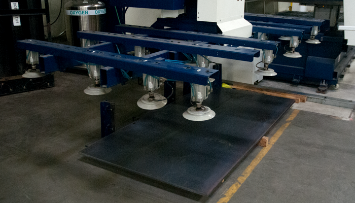
In metal fabrication, moving the metal parts is a major responsibility. Sometimes it can be hard and risky for the operators to carry heavy or sharp metal parts. But stainless steel fabrication, aluminium fabrication, and steel fabrication are all about these heavy and sharp metal parts. So metal fabricators had to look for an easier solution to carry and assemble these risky parts – vacuum cups.
Depending on the size of the vacuum cups, they can carry sharp or thin edged parts for laser cutting, metal rolling, metal bending and big or heavy parts for assembling, welding etc.
These vacuum cups have genuinely brought a revolution to the automation in assembling and carry process.
Vacuum cups, not suction cup
There is a common misconception about the vacuum cups. People mix it up with suction cups. Suction cups are pressed onto the metal part and then the suction cup seals with the part itself because the air inside is expelled. But vacuum cups works differently. A pneumatic vacuum generator along with a venture is employed by the vacuum cup for action. In this process, compressed air is present and they create a vacuum to hold or grip the parts used in a metal fabrication process.
Characteristics of Vacuum cups
Vacuum cup shape, size, durometer, and its tread design all have a major impact in rapid pick-&-place exchange applications. These vacuum cups must have the capacity to clutch the board dependably amid the most stressed points of the computerization’s increasing speed and deceleration stages.
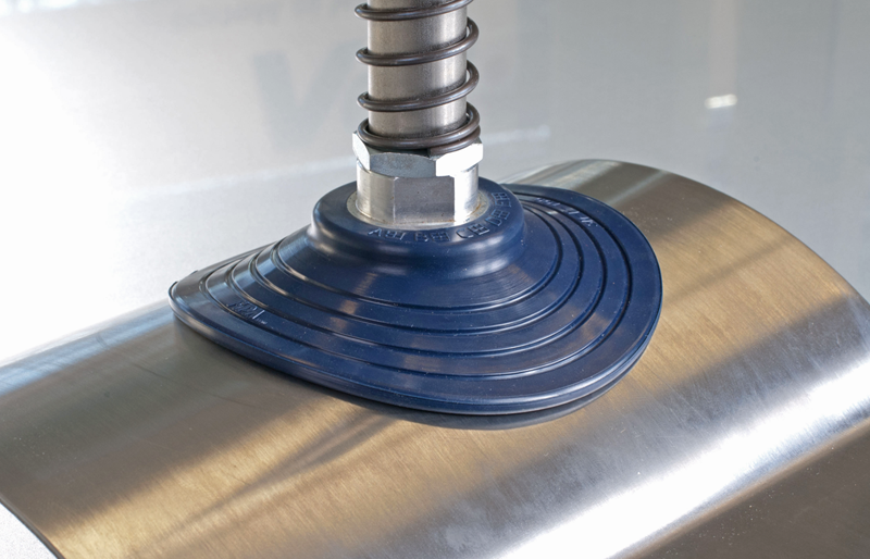
Style and Shape also have its influence. The most used and common vacuum cup has a round shape. Be that as it may, if the cup must grip a sleek rail around any car window or door, for instance, an oval-shaped cup may be required. Ringer molded vacuum cups likewise are accessible for clinging to curved or arched surfaces.
Within these shapes, there are 2 styles: bellows and flat. The bellows-styled vacuum cups are collapsed like the accordion, which gives it the adaptability to pick up things with a sporadic shape or the ones that are not all around lined up with the cup. In these cases, a higher vacuum stream is expected to expel the bigger volume of air from inside. A flat vacuum cup is not as adaptable as the bellow-styled cups. However, they can make a solid grip with minimal air departure.
Durometer is another concern for the vacuum cups. A durometer is usually accompanied to the measurement of hardness in rubbers, elastomers, and polymers. The hardness of most vacuum cups is tested with the Shore A scale. The higher number it gains, the harder the material.
Tread Patterns for vacuum cups are quite distinctive. Vacuum cup providers have made up their own particular one of a kind tread designs that help decide the holding force or grasp of a vacuum cup on the metal part’s surface. A vacuum cup that works in a specific application may not work for others, particularly if the part’s or sheet’s surface is slick dry. Some vacuum cups’ treads are accessible in numerous durometers to get a better grip on the part.
Conclusion: As you’ve realized by now, these vacuum cups are specific to the applications. That’s why metal fabricators need to ensure that they’ve chosen the right one for their need. Otherwise, the production line won’t be as productive as it would have with these simple and small suction cups.


