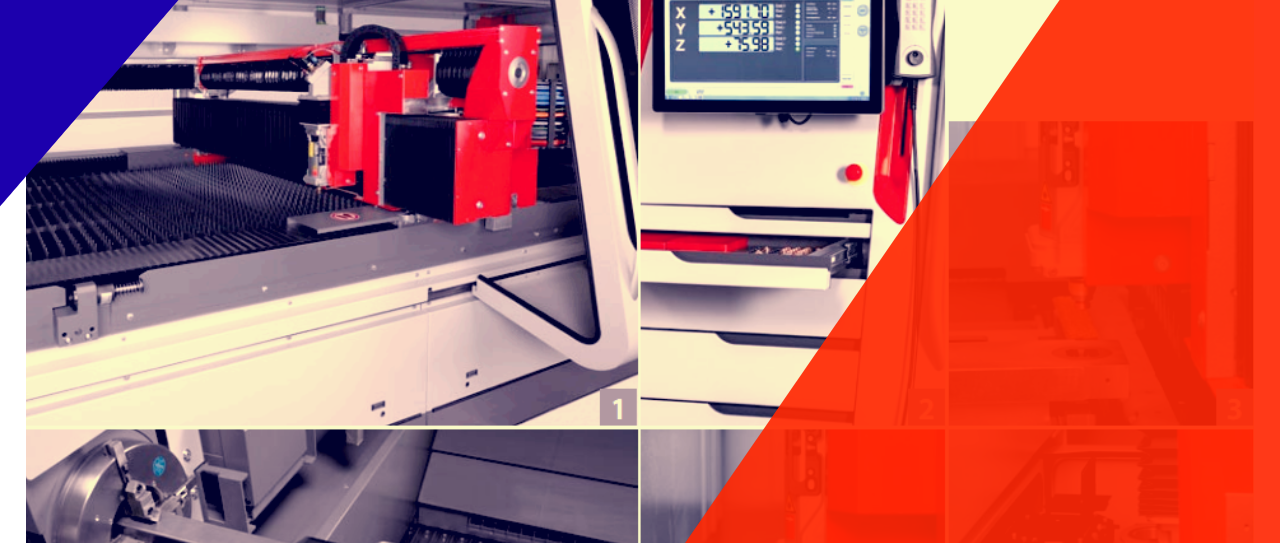
Frequently checking your tools and machine will not only save your money but also save hours of production loss, which can happen if even one of your machine breaks down. Yes, it’s true that machinery problems are very common in stainless steel fabrication, aluminium fabrication or steel fabrication. We see laser cutting machines stop in between a cut, metal bending press brakes malfunctioning badly, welding gears falling apart, etc. in our fabrication shop almost every day. But that doesn’t mean we have to accept those without even trying to prevent the break-downs in the first place.
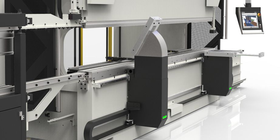
To save the loss of countless hours of production, it’s important to keep tabs on your machine’s performance and check for faults. Each tool or machine used in metal fabrication should be checked thoroughly for faults and performance issues. Where the process is rather easy for metal rolling machines, welding gears, etc. – for the metal bending press brake, it’s somewhat challenging.
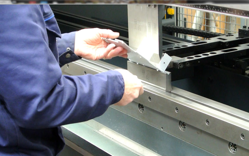
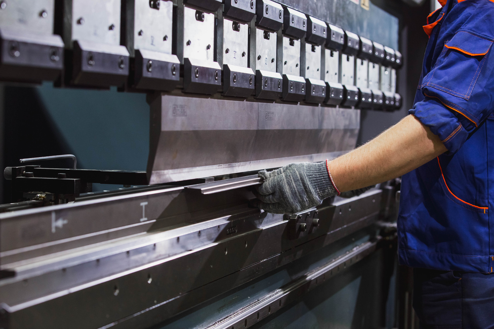
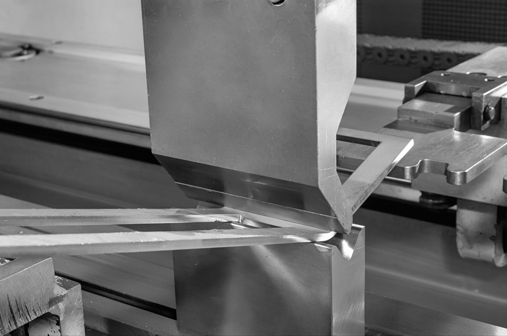
Performance issue with Metal Bending Press Brake
The best way to evaluate the performance of a press brake is focusing on the
- Ram Repeatability
- Reproducibility of backgauge area
- Possible damage on the bed and ram
- Availability of the consistent tonnage
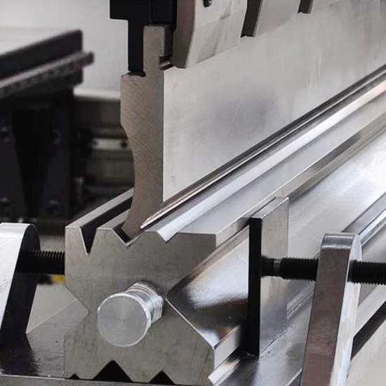
The first 3 of them needs a dial indicator and a mag-base. Check whether the bottom of the ram and the top of the bed is free from any burr or physical damage or not. If there is, your press brake operator needs to clean up the surface with a sharpening stone. But don’t overuse the stone. You are just removing the burrs. Don’t need to put extra effort to make it look like you are modifying it.
Take the dial indicator and the mag-base. Then slowly move them from one end to another while the ram is in a closed position. Doing that, you’ll notice the dial indicator needle is going back and forth as you continue to move towards the minor plain imperfections. There shouldn’t be any movement of the indicator needle move one way while you are moving it towards the center and after that, move to the other way when you start reaching for the other end. If by any chance, this happens, you should know it’s about the ram upset. This type of maintenance requires professional help. Don’t try to fix it on your own.
Then set up the dial indicator again for further reading while the ram is at the bottom. See if the ram returns and gives almost the same reading every time after cycling the ram multiple times.
Next, you need to check is the Tx axis and you can do that by measuring the body if the die you’re about to use and the 2 sets of tooling in the press brake, one at a time. Send the backgauge to the reference position or the origin. Take help of the user manual if you are not aware of the machine. In most metal bending press brakes, it’s four.
Now add half the die body width along the number. Then measure from the front of the backgauge to the front of the die. It should be constant for multiple readings.
Conclusion: These are just the common ways to figure out the recent performing of the machine. For an in-depth analysis, a professional is suggested.
When it comes to metal fabrication, sometimes it’s not easy to get the best angle for work. You may not get the perfect surface for laser cutting operation or you may not have the best view of the part where your metal bending machine or metal rolling machine is tampering. But that doesn’t stop metal fabricators from doing what needs to be done.
Whether it is stainless steel fabrication, aluminium fabrication, or steel fabrication, things will become complicated at times. That’s why you need to be prepared for all situations and know how to get the difficult situations handled.
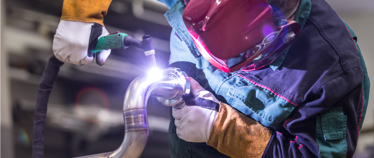
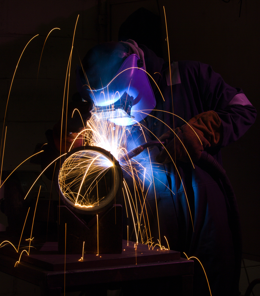
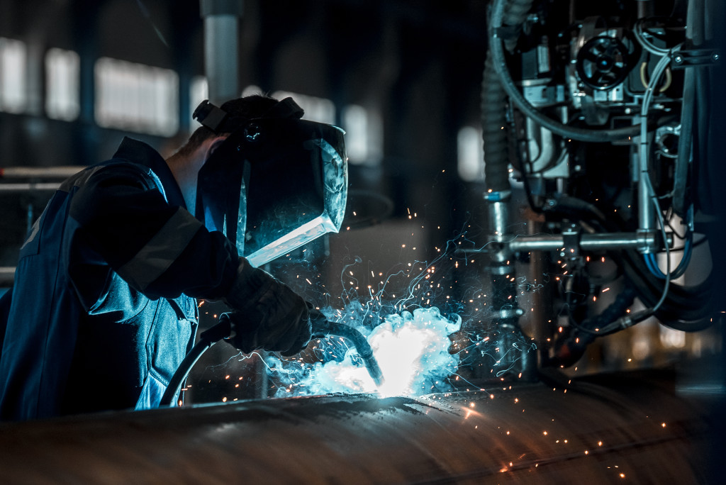
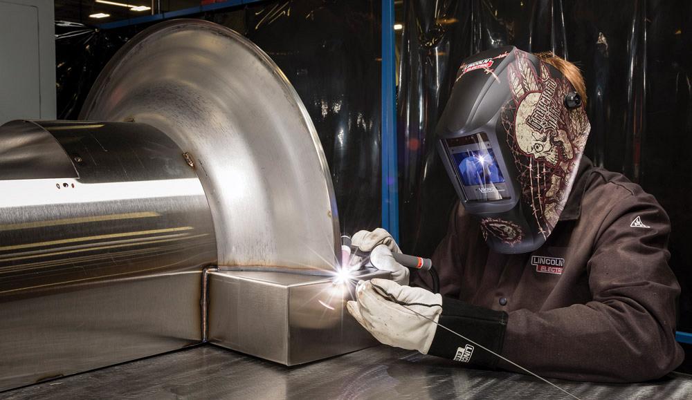
Today, I’m talking about one specific problem regarding metal welding. It’s about handling the welding work when it’s not in a comfortable position. This out-of-position welding is mostly used in big structural industries like shipyards, pipeline, etc. In these cases, you cannot move the workpiece to your comfortable position, which is why you need to do the welding over your head or vertically. And clearly, it’s not an easy process.
Why is it complicated?
The main reason why doing vertical or over-head welding is difficult than regular in-position welding is you are actually working against the gravity. In this case, the liquid-like weld pool tends to drop, which leads to poor welding.
One of the many solutions that people offer to this kind of situation is welding slower. However, lower welding area or heat input may also reduce weld pool fluidity. Although they are effective, these measures also reduce the quality of welding, which is bad for you and your metal fabrication shop’s reputation.
Mistakes that welders make
These are the most common mistakes that metal welding shops do.
- Using a wrong welding procedure, which is clearly not suitable for the optimal application.
2. No being able to adjust the welding areas from in-position to out-position that results in the high amount of heat input, comparatively more than what’s needed.
3. Thinking that the exact same consumables and technique, which were proven effective in in-position welding will also work for out-of-position situations.
Doing it the right way
Some of the welding processes are comparatively easier to use in out-of-position and some are just not suitable. Consider these main criteria for making the decision.
Environment: Welding outside your shop or inside? Gas-shielded technique normally works better inside, while welding forms that don’t require shield-gas are more qualified to open-air work, for example, pipeline welding.
Requirements for productivity: On the off chance that the application calls for you to up & down scaffolding to finish few welds at any given moment, the efficiency of the welding itself isn’t a critical factor. Contrast those sorts of uses with high-volume manufacturing conditions where productivity is basic in general. When welding efficiency is imperative, search for a technique that conveys quicker outcomes.
Skills: A few techniques have an extensive parameter and can be a bit more forgiving of the welder’s technique as well as consistency, which means more forgiving for the out-of-position welds. It might be helpful for less experienced welders to pick a technique that makes it simpler to create quality welds out of position.
Know your customers is the basic rule for any or all business. Whether you are selling a physical product or a software-based service, knowing your target audience will definitely give you an upper hand.
To metal fabrication shops, it’s comparatively more important as satisfying the customers with their work is the priority. Regardless of the material you use – in stainless steel fabrication, aluminium fabrication or steel fabrication, it’s imperative that you meet your client’s expectation. If you cannot satisfy them with your laser cutting project, they will definitely uncheck you from the shortlist for their metal bending or metal rolling works. So, by doing one thing wrong, you are jeopardizing your entire business relationship with the clients.
But how do you avoid this? The answer is simple – know your customers. If you know your customers well enough, you’ll figure out what they want from you and thus you can maintain a healthy relationship, which may lead to other projects in the future.
“How do I know my customer?”
Well, there are many ways. But today, I’ll be talking about one specific, the VOC research.
What is VOC?
VOC stands for Voice of the Customer. This is an activity which can be conducted in a few days/weeks if you have a small and close group of customers in mind. However, it can take months if your client base is massive.
Will The VOC study yield the result?
Metal fabricators who are embarking on the VOC research projects usually have 3 question:
- Is the research worth the money, time, and researches?
2. Is the result credible enough to be taken granted for by my team?
3. Is the study result is efficient in locating where we are lacking and needs improvement?
The answers are yes, only if it’s done properly.
How long does it take to conduct a VOC Research?
It actually depends on your talent and the amount of time you spent on it. Ideally, a VOC research takes almost sixteen weeks or so, if you are doing it alone. However, if you think of tagging a partner along, it might save you few weeks. Generally, you and your partner should spend 20% to 30% of the time to finish this research. A key stakeholder for occasional support may be helpful to the entire project.
Conducting this research
To get started with this research, you will need to record some interviews and the whole project can be divided into 5 steps.
Step 1: First of all, it’s crucial that you establish the project scope and obtain the approval.
Step 2: In this step, developing the “Voice of Customers” interview plans is necessary. Keep your audience in mind for this part.
Step 3: Next step is to conduct all the VOC interviews as planned in step 2 of the process.
Step 4: Here, you will need to identify the VOC needs and then sort out the VOC needs to develop a Primary Needs Table.
Step 5: Finally, you’ll need to conduct the broad customer rating email survey that will help you build the Market Opportunity Map.
Stainless steel fabrication, aluminium fabrication or steel fabrication, no matter what the material is, each metal fabrication process require a specific set of equipment and supplies. Laser cutting requires Depron foam, ABS; Metal bending requires angle bender, press brake; Metal rolling requires roller, cloth, etc. Similarly, welding requires gas bottles, consumables, power sources, and other equipment.
The welding shops get their supply from distributors. While many believe that the distributors’ job is to supply these essentials only, there are few who believe the distributors have something more to contribute to the whole welding process and the welding shop.
1. Advising and Providing Analysis
To be honest, you can buy the supplies from anywhere. If you order the electrodes tonight online, you’ll get them tomorrow.
When you can get the supplies from almost anywhere, why will you go to a specific distributor for the supplies?
Unless the supplier is offering something more than the power sources and electrodes, metal fabricators won’t think of sticking to one dealer for long. That’s why many suppliers are offering out-of-the-box supports with the equipment. For example, Airgas offers their customers some exclusive data and analysis of the market that may be helpful to finish the operation efficiently.
This is how they maintain a long-term relationship with the clients. This exchange of data, program or analysis helps both the welding shop and the supplier.
2. Use the Expertise and Support beyond the purchase
Local supplier or distributors of these supplies should not be “just sellers”. They should be more open to helping and collaborating, not because they need to. They must do it because they should.
These suppliers have years of experience with the operations and they know their ways around welding. The problem you or many other welding shops are facing today have been solved by these local suppliers way back.
For example, if you are facing a problem regarding the removal process of abrasive from your workstation, the suppliers can help.
Welding shop owners don’t even know for how long the distributors are helping other shops in situations like this.
These local dealers can also play a role of advisors to the welding shops. Since they are handling the supplies for multiple welding shops, they know about the most frequent obstacles in this operation. They may even know about some of the easy solutions to the complicated problems.
If the suppliers decide to share their expertise in handling difficult situations with welding shop owners, the relationship between may grow and benefit both of the parties.
3. Test Before Investing
Every day hundreds of new tools, consumable, and equipment are introduced. But if the welding shops don’t know how they are going to affect the results, there’s no guarantee that they’ll buy them.
Blind buy may work for your perfume or mobile phone but it won’t work for the welding operation. However, the supplier can offer trials to the welding shop, helping them understand the new technologies that are being introduced to them. And if the shop owners think that these new items have the potential to increase the productivity of the operation, they’ll certainly buy from the distributors.
Like laser cutting, metal rolling, welding, metal bending, etc. the rotary cutting has developed since its introduction in the early 20th century. From a simple method of cutting metal parts for any stainless steel fabrication, aluminium fabrication, or steel fabrication process, it turned out to be one of the most effective cutting methods in pipe and tube production.
Although in a sense, the rotary cutting is simply a motorized form of plumber’s tube cutting, it still managed to place itself on a firm position in the metal fabrication industry over the years.
How Does It Work?
The tube or pipe is placed in the roller while the rotating cut-off blade engages the pipe or tube. This causes the tube to spin and when the pressure is applied downwards to the cut-off blade, it goes through the wall and simply parts it.
In this process, no material is wasted because the tube is parted, not cut. Besides, it eliminates the need to clean the workstation every time you process a tube, which is why this type of chipless cutting is very efficient for metal fabricators.
Different Applications:
Rotary cutting can handle different tube and pipe lengths and diameters. That’s why it is used in metal fabrication, automotive, heat exchanger, sprinkler, conveyor, game equipment, cylinder manufacturing, nipple & pipe industries and most importantly the tube production industry.
As for the use with different materials, rotary cutting is suitable for almost any kind of metals like steel, brass, copper, aluminium, stainless steel, titanium, etc.
Machines
There are two primary styles for rotary cutting machines.
Manual: The manual ones are an economical option for metal fabrication shops with intermittent cutting operations. As the name suggests, they require an operator to handle it throughout the process. So the quality of results depends on the operator’s experience and capability. However, these machines are only suitable for short runs.
Air-Operated: These are more advanced and requires minimal adjustment. They eliminate operator’s fatigue by automatically adjusting the cutting speed, the position of the head assembly, air pressure, etc. The units can maintain the same cut from the very first one to the last one of a production line.
Accessories with the Machine
To increase the efficiency of rotary cutting, there are a number of accessories available in the market.
Length Gauge Assemblies: The standard length gauge assemblies provide a good stop for the repetitive cutting of material. Here, the assembly allows consistent and repetitive cuts throughout the production run without re-measuring.
The automatic length gauge assemblies allow a good stop for repetitive cutting of the same material and automatically initiate cut-off cycle once the length of that material is calculated.
Cutter Block Assemblies: For specific pipe and tube diameters, the cutter blocks assemblies are available in different sizes. They provide support for the machine while the material is being cut.
To use it properly, the operator needs to ensure the cutter block rolls are spaced so that the pipe or tube diameter is cradled one-third of the way into the rolls. Usually, by spreading the rolls from the initial position, the operator can reduce OD burr. But for reducing ID burr, the rolls need to come closer.
In stamping operations, selecting the wrong tool is literally the worst thing that can happen to any metal fabricator. One such mistake can decrease 10% of that day’s production and as a metal fabrication shop owner, I know how that will feel. Whether it is stainless steel fabrication, aluminium fabrication or steel fabrication, increasing your shop’s productivity might be the most driving factor for your everyday update and tool upgrade.
But avoiding this mistake is not easy as stamping operation offers a good number of options, even more than laser cutting, metal bending, welding, metal rolling, etc. However, it is not impossible to avoid.
Improving ROI
Tooling for specific operations depends on some factors related to the application. Mostly it depends on the material type, the machine tool, thickness, production speed, tolerance, lubrication, etc.
Different choices identified with these variables can enhance device life. It’s crucial that each circumstance is treated with the uniqueness it requires as not one particular task is the same as another.
After evaluating your die plan and application, survey the gear and check that resistances can be held at the speed needed to expand productivity. This incorporates assessing the press to make sure the precision and paces are feasible for the generation prerequisites proposed.
Extreme Punching
High-volume and High-Frequency stumping are actually the industry norm. However, the increasing popular exotic material can burst the standard tooling, wearing dies and punches faster than usual cold-rolled aluminium or steel.
Tackling tip wear issues is just a single aspect in maximizing tool’s life. Numerous applications stress tooling in the places other than its tip. Sometimes the failure part is the head. This head breakage can happen amid snap-through, boring impact, or punch withdrawal.
Coating Technology Improves Punch Life
Coating is perhaps one of the best and effective way to boost any tooling performance whether it is stainless steel fabrication, aluminium fabrication or steel fabrication. This is especially a stone-like truth for punch cases because the coating provides impact relief during the initial application.
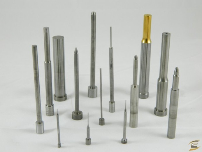
The punches are usually treated with different kinds of coating. These coatings are engineered to boost the performance of stampers.
For the last 2 decades, the coating centers have reached everywhere in the world, for a good reason of course. But matching the coating to a specific application is sometimes overlooked. Ideal Titanium Carbo-Nitride or TiCn and Titanium Nitride or TiN coatings are the most common ones that are globally used by all metal fabricators. Although any of these will ensure the productivity gain for your application, to get maximum efficiency, it’s a must to choose a coating designed specifically to suit that application.
The Underline: High-Standard Manufacturing
As I’ve said, tool failure is perhaps the biggest threat to stamping operation. You simply don’t have the luxury to bear a premature head breakage or any other situation where your production line stops. So if you need to prevent these unpleasant events, you need to invest in high-quality tooling with a minimum cost of ownership. Without using standard tooling, you cannot expect smooth operations in your workshop.
Metal fabrication is a jar that is filled with different fabrication processes and closed with the equipment needed to pull those off. In most cases of manufacturing a whole product, multiple stainless steel fabrication, aluminium fabrication, and steel fabrication processes are needed. Laser cutting machines cut the parts, metal bending and metal rolling machines give them the required shape, and welding joins those parts to form the whole product. But it’s all just too much for. You need to go from one station to another for each process.
It not only takes time but also causes injuries to the operators because moving these parts are risky.
But the risk of loading and unloading of the parts decreases when all these can be done under one roof, specifically, one station.
Derived mostly from Toyota Production System, the lean manufacturing is developed to work relentlessly to remove all and any no-value-added parts from the part.
The ultimate lean metal fabrication process is actually a matter of unloading and loading a properly finished assembly from the very same machine it all started.
Putting The T
Usually preparing pipes for plumbing subassembly needs at least 2 different machines. One for cutting and one for making the collar Ts.
T-Drill developed a hand-held tool and bit specifically for the collars or Ts. In addition to the hand tool, it also makes other machines similar to the auto-feed drill press.
This is a single-station machine, which makes collars on pipes. To keep up with the time, the company expanded their line of products to offer programmable machines with automated feed table. Once the unit is done installing, the collaring head, linear T location, programming rotary, and loading the tube into a machine becomes a one-step process. The operator runs the program and the rest it up to the machine to finish.
An Automated Situation
Metal fabricators, especially pipe and tube manufacturers always wanted a solution that would help minimize the production time and risks. For pipe manufacturing, fabricators always wanted a setup that can cut the pipe and make the Ts on the same unit. Eventually, they got what was just a concept.
The unit from T-Drill would be fed the preloaded rack and when the rack is clean, it won’t stay idle. As the rack gets empty, the machine will fill it with new stash and the finished parts will go to the second part of the setup where the collar Ts will be done. The machine will be programmable to do all this. Manufacturers will not need any experts for the programming. The setup will straightly get its instructions from a database in .csv format.
Cutting, Drilling, Pulling, and Measuring
The machine has a tool library and a tool changer. The tool library can hold up to twenty different tools and these tools range from regular drill bits for general holes, pull collars made for plumbing, tapping tools for the furniture, and large diameter hole saw up to collaring heads. This interchanging multiple tool setup will make the pipe and tube preparation process more productive and efficient. Sooner than later, this machine setup will be embraced by all in the metal fabrication industry.
Metal fabrication industry is filled with challenges. Whether it is stainless steel fabrication, aluminium fabrication or steel fabrication, metal fabricators always find themselves at a situation where they need to use their knowledge and wit to overcome the obstacle and get the workpiece done perfectly.
For laser cutting machines, welding equipment, metal rolling and metal bending press brakes, the difficulties and challenges are somewhat limited. Some technical help from the maintenance crew can get the things done for you. However, after sawing, the challenges are less like challenges and more like irritating incidents. To be honest, there’s not much technical stuff that can go wrong while the process. But still, the sawing is one of the most annoying and time-consuming metal fabrication processes out there. This is simply because unlike laser cutting, metal bending, welding, and metal rolling, sawing challenges are not limited. If I was asked to put together a list of things that can go wrong in the sawing process, I’d be up all night. Fortunately, no one has asked me that.
So today I’m only going to address the issues regarding broken teeth and blade breakage in the sawing process.
Broken Teeth
- The break-in procedure of the blade you took for sawing may not be right for it. In such cases, the teeth are certain to break. So use a break-in method that is recommended by the manufacturer.
2. Each blade has its breaking point. If you don’t follow the recommendations for speed and use the blade at a lower speed than recommended, you might lose their teeth.
3. No following the optimal pressure for the saw can be a good excuse to get the teeth out. So, don’t use more pressure than you are told to.
4. When you put too much pressure with a slow momentum, the teeth get ripped up from the blade because they cannot sustain such pressure at such low speed. This is called teeth jump cut.
5. If the lubricant isn’t sufficient, accidents can happen. Besides, only ensuring its presence is not enough. You need to make sure the ratio is right and you are using the right lubricants for the application.
6. It might not be a shock to you that a hard workpiece can cause your blade to spill out its teeth.
7. Sometimes choosing the right blade can make a heavy impact on the sawing process. You need to guarantee that the blade you are going to use can cut the material in your table.
8. Sometimes if the workpiece is not clamped with the workstation properly, it can spin while sawing. In such case, there’s a high possibility for your blade to lose some of its teeth.
Blade Breakage
- If you don’t set the blade tension to the right value, you saw blade might break. That’s why remember to check the manufacturer’s instructions before setting the parameters.
2. The feed pressure can also break the blade besides breaking the teeth. That’s why never set the pressure too high.
3. Insufficient lubrication can as well lead to blade breakage.
4. Inadequate blade support is another reason why most of the sawing failures occur. So make sure it is tightened and aligned properly
- Adjust the wheel alignment to prevent the blade from rubbing on the wheel flange.
With the endless advancements in stainless steel fabrication, aluminium fabrication, and steel fabrication, especially in the metal bending machines, it appears that numerous still endeavor to locate that flawless, repeatable setup. Notwithstanding, a typical issue is that numerous fabricators ignore material science. As opposed to depending on the tooling set to carry out its activity, numerous make-up for worn tooling or an inappropriate setup by over-using the machine’s powers or by shamefully utilizing the machine’s capacities. Attempting to substitute power for a legitimate tooling setup frequently causes more mischief than great.
It can be argued that the abuse of a machine in metal fabrication, regardless of the process, even a laser cutting machine or metal rolling machine, implies underuse of the tooling. This frequently is the situation in numerous metal bending circumstances. At times, the application is troublesome; it’s as basic as that. In any case, much of the time, worn and insufficient tooling is the most widely recognized reasons for setup trouble, particularly with routine metal bending employments. Since even the most experienced setup specialist battles without legitimate instruments, this is the primary driver of setup challenges.
Understanding the Tooling Factors
Like most tooling used for different metal forming applications, these rotary draw metal bending tools usually are specified to suit in specific metal bending applications.
Assessment of this scope of the application’s necessary tooling considerations usually leads to the single and optimal tooling set suitable for the application. When it is set up properly, the set will begin to yield great bends.
Better Grip for Preventing Wrinkles
The main motive of mandrel metal bending is to avoid the wrinkles, not from removing them. The clamps should be sized perfectly and work properly because most of the time, these clamps slippage is the cause for wrinkles. Proper grips is a must for preventing these unwanted glitches.
Besides considering the material, WT, DOB, OD, CLR, metal fabricators should remember that less bendable materials, by and large, require longer clasps, so the material kind is an essential thought while deciding the right incredible.
Using Pressure Die-Assists Instead of Carriage Boost
Some full CNC machines are outfitted with a carriage boosting include. The Carriage boost utilizes the collet to drive material into the curve amid the metal bending process. This additional power defeats the drag related to the pressure die and diminishes weight on the clamps. Thus, this capacity regularly is utilized to make up for clamps that are too short for the application.
A by-product of the carriage boosting is that it likewise encourages the material to the intrados of the twist, a territory where wrinkles officially have a tendency to happen. Sustaining extra material into this district displays a more noteworthy test for the mandrel and wiper die to survive, quite often requiring extra direct pressure at the pressure-die.
At last, utilizing carriage support requires a high-pressure setup that altogether annoys the regular stream of material amid the metal bending process. Not exclusively are the subsequent setups more hard to duplicate, yet the required bending powers make altogether more wear and tear on both the machine and tooling. Consequently, it’s best to utilize the carriage boosting sparingly and just when completely required. It’s best to utilize pressure die help to help move material along the extrados of each twist.
Whether it is stainless steel fabrication, aluminium fabrication, or steel fabrication, the processes fail all the time. Laser cutting machine can leave bruises on the edge, metal bending press brake can stop in the middle, welding can mismatch, metal rolling can go sideways – anything can happen. And metal fabricators are always prepared for this kind of stuff because they know failures are a part of metal fabrication. However, draw fails are one of the most disturbing ones that metal fabricators have to face.
Drawing has been one of the most integral parts in the metal fabrication industry, especially in tube fabrication process. Drawing can change the part’s or product’s physical characteristic, like changing Outside Diameter, Inside Diameter, and also the mechanical properties.
But the draw dies failures are a big problem that metal fabricators need to sort out. It’s not easy. However, if you know the reasons behind these failures, it’s easier to get around with the process.
Low-Quality Tooling Material
The reason for each carbide instrument is a preform, actually, a semiformed part made with sintered carbide powders that a dying company uses for making the draw tooling. The regular sizes, accessible in R assignments (R-5 up to R-17), keep running from 0.6250 to 4-inch OD. Die companies mostly rely on preform quality because they polish and pound the unpleasant external surface of the device. Obtaining a low-quality preform brings about sat around idly and assets in wrapping up. These die companies presume a misfortune when the preform needs additional work to clean it, & their clients assume a misfortune when the instrument bombs underway.
What adds to a brilliant preform? The essential factor is sintering, the procedure that changes squeezed carbide powders into a strong piece. Temperature, weight, and time are the basic parameters, and they need cautious control amid this procedure. These parameters depend on material review and part estimate. Lacking sintering can prompt different metallurgical imperfections, for example, extensive grain structure, porosity, and inadequate carbon.
Substantial Die Constructions
The two essential parts of any carbide dies are the insert and the case. This case serves 2 functions: gives mechanical help, and it retains warmth from insert then passes it to the dies blocks. Some die squares are water-cooled to give significantly more warmth retaining limit.
The productivity of warmth exchange involves contact region. In the event that the contact region between the insert and the case is inadequate, the greater part of the warmth produced by the drawing procedure is consumed by the inserts, and in the long run, it overheats eventually and falls flat. The carbide embed ought to be centerless-or harsh ground to give more reliable contact the case than the inserts would have on the unpleasant cored state.
A prominent approach to join the insert for the situation is to put the inserts into the case and then peen the case’s best edge over to anchor the insert. However, this technique isn’t normally utilized and dies developed in this form regularly fall flat.
Mechanical Failures
At the point when the draw seat administrator has a drawing issue, the most well-known response, for all intents and purposes a reflex, is to be faulted the die. An underlying driver examination incidentally uncovers a die issue, however regularly the inconvenience started somewhere else.
Pieces of information to the inconvenience may sit on display around the die zone, or they may hide behind the draw seat anyplace upstream of the area-die; it’s a matter of taking a peek at the equipment, deciding how it was planned to capacity, and contrasting that with how it truly functions.


