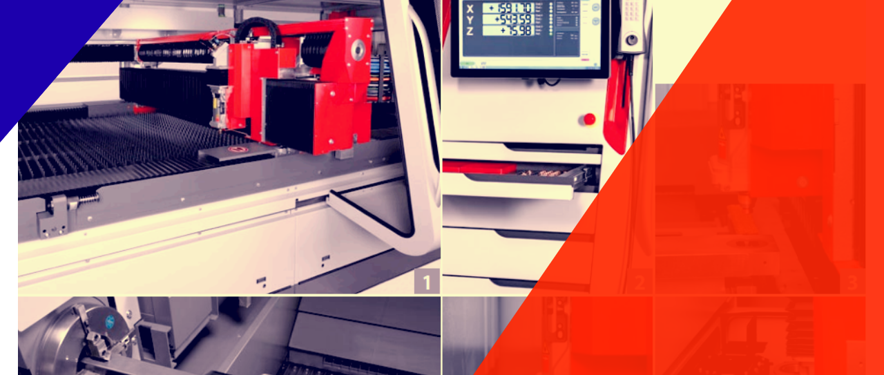
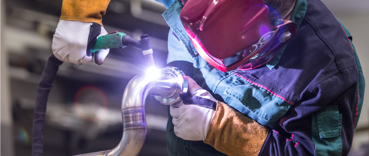
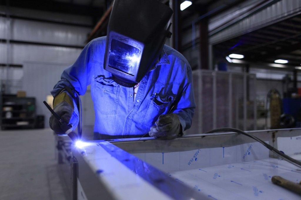
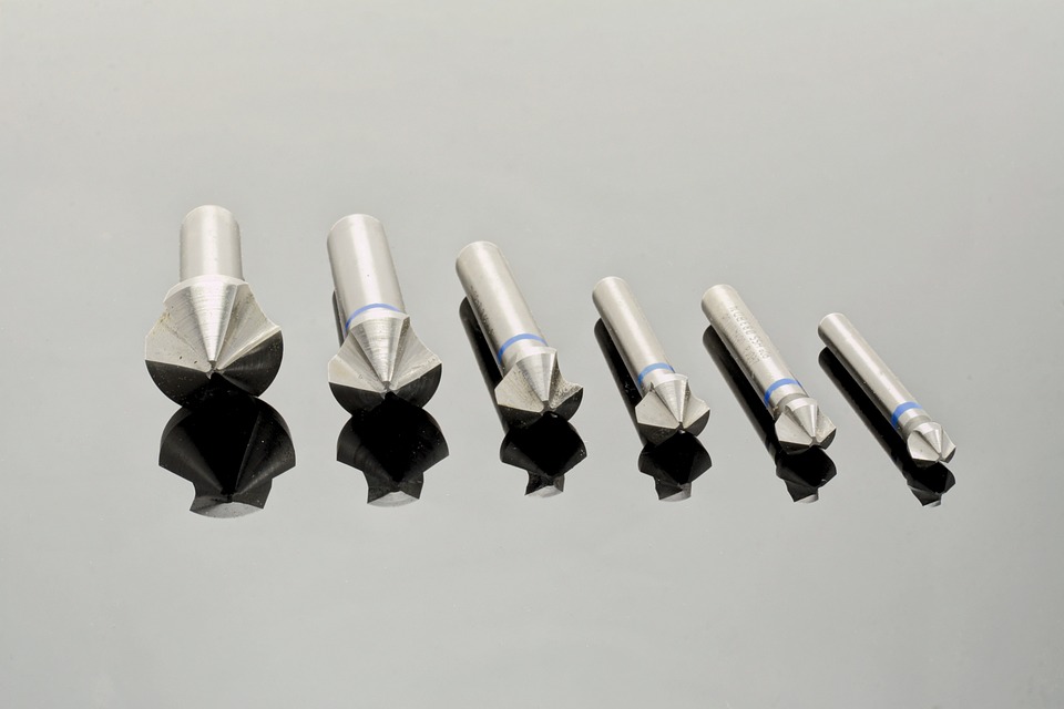
With most innovations in metal fabrication, like advanced laser cutting machines, automated press brake for metal bending, bots used for plasma cutting, or even the slightest progression in metal rolling, etc. didn’t stop with those tools’ advertisement. Tools have developed to grasp augmented reality and even live to weld in an offer to offer more value to instructors and a few manufacturers. Indeed, these propelled welding preparing tools are progressively being taken a gander at not only for essential aptitudes improvement but rather welding abilities approval. Early successes in stainless steel fabrication, aluminium fabrication, and steel fabrication propose that these advancements may bode well for those private-sector organizations that need to qualify welders applying for specific employment or to decide whether welders have aced certain abilities before they can advance to another position.
Augmented Reality World
According to Calverley, the Director of Education, this augmented reality system actually gives them an opportunity for a getting a feel for the muscle memory as well as movement that it can take for the specific welding skill.
Calverley told the teachers have come to like the augmented reality innovation since it is anything but difficult to set up and run. They are additionally ready to redo the educational modules, create assignments for understudies, and run reports to monitor understudies’ authority of welding abilities.
Real World Influences in Welding Training
Scott Laslo, a teacher, said that this preparation framework principally has been utilized for aptitudes appraisal. Educators get a complete thought of where another understudy entering the welding educational modules is with welding aptitudes so the understudy can be set in the suitable classes. The unit is likewise extremely helpful in giving a quantitative step of how well the understudy has played out certain welding forms. As a result of the innovation, understudies have possessed the capacity to make welding portfolios, which contain pictures and documentation of all the welding they have learned.
Additional energizing, as indicated by Laslo, is the mentor’s capacity to make a welding procedure specification or WPS that can be utilized as the “best quality level” for different welders rehearsing a similar procedure.
No Training Techs Make Their Mark
Some more seasoned fabricators may laugh at the possibility that these sorts of training gadgets can convey an indistinguishable taking in understanding from welding in a stall for quite a long time. Yet, look into recommends that all these grizzled veterans at the shop floor aren’t right.
In the research paper in 2011, the Virtual Reality Integrated Welder’s Training, 3 designing students of Iowa State University looked at two training gatherings, one that utilized a mix of virtual instruments and customary welding training educational programs and one that got their training entirely in welding corners. The specialists took in the accompanying:
1. The group that utilized virtual reality devices showed more elevated amounts of group learning and cooperation than the other group.
2. Virtual reality condition enabled the learners to set down a greater number of all the weldings than their partners in the other gathering.
Difficulties are a part of metal fabrication. Whether it is laser cutting, metal rolling, metal bending, or welding, there’s always a problem with fabrication processes. Weld porosity is one of them.
Weld porosity is not uncommon in stainless steel fabrication, steel fabrication, or almost all over the metal fabrication industry, especially in Aluminium fabrication. So, today, I thought of talking about the weld porosity in aluminium fabrication shops specifically.
Before that, you should know the reason for weld porosity.
• Insufficient pre-weld cleaning. You should evacuate all lubricants, greases, oils, et cetera from the weld region before you weld.
• Airflow in the weld region. On the off chance that air is moving sufficiently quick for you to feel, that is excessive. Close all entryways and windows and power off all fans inside the weld zone.
• Gas-nozzle-to-work removes that is too long. Keep it as short as could reasonably be expected.
Imagine a scenario in which you are sure you have these factors under control, however, despite everything you have porosity. What now? Investigate the accompanying potential reasons for porosity that are not as typical, but rather do even now happen.
• Leaky water-cooled welding weapon. Breaks can happen with a firearm that is exhausted. All the more regularly spills happen in light of the fact that the firearm has been dropped or generally manhandled. Try not to expect that the weapon is leak-proof in light of the fact that you don’t see water dribbling out the end. Indeed, even a hole too little for you to notice will cause porosity. Certainly, think about utilizing an alternate weapon.
• Poor shielding gas quality. It is feasible for the argon shielding gas to contain water or different contaminants. It doesn’t occur regularly in light of the fact that the real gas providers are exceptionally strict about gas quality. In any case, attempt an alternate jug of gas just no doubt.
• Surface contaminants on the welding wire. Aluminum wire must be greased up amid the assembling procedure, or it will break amid drawing. It is up to the wire producer to make certain that the most of this lubricant is removed before it is spooled. Like gas providers, the most part of the real wire makers completes a great job of this. On the off chance that you are encountering porosity, take a stab at changing the wire spool to discount the likelihood of a terrible spool of wire.
• Oil as well as water in the shop air supply. All shop air supplies contain oil and water. In the event that it gets onto the weld territory, it can cause porosity. Ensure there is a decent channel in the shop air supply close to the welding zone. Likewise, be cautious about what course the fumes from air instruments are pointed. I used to be in a decent shop that was having porosity issues. The fabricator was utilizing a pneumatically controlled wire brush to clean the weld between passes. The issue ended up being that the air device debilitate was coordinated directly into the weld groove. Since the shop air contained a ton of water and oil, the apparatus wasn’t cleaning the weld; it was tainting it.
• Gas fittings in poor condition. Make certain that all gas fittings are tight and that gas hoses have no breaks or parts in them.
• Water spills caused by ill-advised hardware, setup. On the off chance that you are utilizing a water-cooled weapon, make sure to utilize a water cooler. Never run the water supply to the weapon straightforwardly from a city water outlet and after that to a deplete. Why? Since in warm climate the water will be colder than it is when utilizing a recycling water cooler, which can cause clammy, moist air to gather inside the weapon hoses, bringing about a water spill.
If you didn’t know already, IIoT is elaborately written as Industrial Internet of Things. But what is IIoT and how to use it in the stainless steel fabrication, aluminium fabrication, and steel fabrication industry remains somewhat unknown till this day. However, we can be sure that it’ll be evolving with each failure and success of the early adopters in metal fabrication.
IIoT can turn into a center device in your production and maintenance activities for laser cutting, metal bending, welding, metal rolling, etc. A genuine risk exists that IIoT disappointments can prompt generation disturbance, quality issues, worker injuries, or deaths. Understanding this, IIoT offers some fantastic opportunities. Chances are it will be anticipated from numerous providers sooner rather than later.
IIoT guarantees to:
• Improve repair and maintenance booking for more noteworthy plant dependability.
• Support the production collaboration and administration crosswise over supply chains.
• Support decision takers with present and exact data about production and machine status.
• Autonomously alter hardware to streamline dependability and effectiveness.
With such opportunity, however, there comes risk that you need to manage:
• Network security is basic to forestall malignant disturbance and loss of focused data.
• Successful usage relies upon a high level of dependability and steadiness in current assembling tasks.
• A good amount of skills are required to keep up the honesty of both the data sorting and the production procedure.
• System blunders can prompt employee injuries.
Adopting IIoT
Timing your reception relies upon your present abilities to observe and deal with your generation and upkeep exercises. Right now is an ideal opportunity to complete a “gut check,” strengthen your qualities, and take out your shortcomings. The better you can oversee and gain from your present data, the more prominent your likelihood of accomplishment when arranging multifaceted nature and a tidal wave of information begin coming in your direction.
To get ready for coming changes in your plant information and checking you should ace the accompanying.
• Implementing a prescient upkeep program.
Likely one of the best advantages of IIoT will be its capacity to warn you to conditions that may prompt disappointment. You can fundamentally enhance your plant unwavering quality while lessening your upkeep costs now, most likely with a portion of the instruments you as of now have.
• Monitoring your gadgets and focusing.
You most likely as of now have tonnage screens and other checking gadgets. On the off chance that you explore the manifestations of out-of-ordinary working conditions, you’ll see that vibration, commotion, and oil observing can caution you to potential failures before they happen.
• Learning how to change over information into helpful data.
Transforming crude information into profitable data requires learning of your creation condition, the capacity to characterize a populace, a solid example from that populace, and the capacity to produce and examine the example’s measurements.
• Talking to your store network.
Examine designs and issues with your clients and providers. You’ll see that they have indistinguishable worries from you do. Keeping an open line of correspondence causes you intend to live up to your production network’s desires.
In the U.S. materials manufacturing plays a massive role in the country’s industry. This includes all sorts of metal fabrication processes like laser cutting, metal bending, metal rolling, and any other stainless steel fabrication, aluminium fabrication and steel fabrication processes. Many of the products of this manufacturing ecosystem include tubing, angles and flat sheets that are about 3/16-inches thick. There has been some debate over the best methods of producing these think welded products. Therefore, a lot of consideration is required and an analysis of the application of the product must be done before determining the best method of welding, shielding the gas, and electrodes to use. A lot of factors are brought to light once a requirement analysis has been done, such as the base material type, its thickness, and condition. Additionally, welding positions and the equipment available to weld the materials also affect the overall decision on the method of welding.
There are some precautions necessary when welding thin materials. Some of these include minimizing distortion and splatter. An additional concern is to ensure a top quality fusion and proper weld without burning through the material.
For plain carbon steel
In the case of plain carbon steel, it allows for a wide range of welding techniques. For some of the thinner materials, gas metal arc welding (GMAW) is recommended in short-circuiting transfer mode. Another option comes in the form of using pulsed GMAW. This, however, requires the use of a shielding gas with high argon content. The use of pulsed GMAW offers the welder more control and a wider range of operating parameters while generating a much lower amount of splatter. Although pulsed GMAW has these benefits, it is not always financially justifiable due to the high cost of the equipment required.
Flux-cored arc welding (FCAW) is another popular method, however, it is not ideal. During the weld, it produces a protective slag layer that must be removed. It also produces more spatter and smokes compared to GMAW.
Finally, the gas tungsten arc welding (GTAW) process. Using this method is perfect for producing high-quality welds without spatter. However, this method requires higher skilled welders and the use of 100 percent argon gas as a shielding gas is a must.
Methods for stainless steel
The primary difference welding plain carbon steel and stainless steel comes when matching proper filler metal to the base material. The use of shielding gases remains similar. For GMAW, a gas with high argon content is required. In the case of FCAW, just like carbon steel, stainless also requires 100 percent carbon dioxide gas or a 75 percent argon with 25 percent carbon dioxide blend.
Aluminum is a different matter
In the case of welding any of the other materials, a clean weld joint is of utmost importance. This is not the case for aluminum as it actually benefits from a pre-weld or brushed joint due to the presence of the heavy oxide layer.
There is no absolute method when it comes to welding, however, the above should set a proper example of choosing the correct method depending on the circumstance.
When engineers noticed a shrapnel getting welded tanks thanks to high velocities, DuPont patented a controlled explosion technique in the 1960s to weld together two workpieces that were difficult to weld together using normal methods. By eliminating problems such as different melting temperatures of different materials or the mixing of metallic compounds that affect the quality of the weld, this method can be used to weld together materials that previously proved to be very difficult or even impossible to weld. This could potentially boost industries involved in metal fabrication, especially stainless steel fabrication, aluminium fabrication and steel fabrication.
In explosion welding, a clean surface is left behind on the two base metals due to the violent explosion. The pressure forms a high-quality weld between the materials. Although, a very effective welding technique, it is not very practical as it cannot be adopted by all fabricators easily.
A modern iteration
In 2011, Professor Glenn S. Daehn and his research scientist Anupam Vivek were working on electromagnetic forming, a process involves a large pulse current sent through a solenoid coil from a capacitor. Forces from the two opposing electrical fields of the two materials caused a forming action.
Those initial experiments have since then produced a process known as vaporizing foil actuator welding (VFAW). In principle, this method of welding is the same as explosion welding wherein two materials are forced together using high velocities in a controlled way. This is why both methods are classified as impact welding techniques. However, the main difference lies in the type of force that pushes the workpieces together.
Unlike in explosive welding, the VFAW uses an intense and sends it into a foil. That foil is placed between an anvil and the flyer. That is the base material that is to be pushed into the other base material, also known as the target. The flyer and target are separated by a small standoff distance through which the flyer moves in order to impact the target.
Bringing it to the world
To bring this technology to the industrial market, the researchers at OSU have been working with different industry and government partners some of which include industry giants like Honda and Ford. Moreover, the researchers have teamed up with Coldwater Machin Co. in Ohio to create a pedestal machine that feeds the foil actuator material under the flyer base material.
As of now, the team faces a significant challenge. Currently, foil coupons are fed into the work area by a coil. Once the weld is done, the coupon is vaporized. However, some of the foils are in a plastic packet, which, once the foil has been vaporized, leaves behind some debris which has to be cleaned out. Right now, they are developing a way to keep that area clean.
Although the OSU team is currently focused on using this technology in the welding front, collaborators see potential use in other production environments such as metal bending, and metal rolling and cutting, which might prove to be more effective than laser cutting.
Every metal fabricator needs technology to get things done. But that’s not tough to manage if you are willing to invest on the technology. So what separates a good metal fabrication shop from a bad one?
Well, it’s the employees.
In this day and age, everyone needs their work done within the shortest amount of time. So metal fabrication shop owners are bound to invest in top-notch technology and increase productivity.
These machines are the heart of every stainless steel fabrication, aluminium fabrication, and steel fabrication processes. But you need a brain to guide these machines and the machine operators and workers fill that role.
So unless you have an excellent team of skilled workers, you are handing over Superman’s power to Lex Luthor. And if you are a pop culture fan, you’d know that’s not a good idea.
So, if you think that handing over the powerful machines to your untrained employees is not a bad idea, then you should get your head straight. There’s no doubt that the advanced laser cutting machines, metal bending, and metal rolling machines are way too much power in incompetent hands of your employees if they don’t know how to get things done.
Yes, I agree that modern machines are developed to be simple and easy to learn or operate. But they are extremely productive and the workflow is smooth with their involvement. However, these days, customers demand speed. In some situations, 5-6 weeks of turnaround time is not ideal anymore. But all those automation and advancement give a lot of power to the inexperienced workforce who aren’t engaged.
To be honest, you simply can’t make a metal fabrication process fool-proof. A careless algorithm or even a job routing fault can lead to a pile of unnecessary and incorrect parts fabricated in a rush. That’s why you just can’t afford to have an unskilled team in your metal fabrication shop.
And believe me when I say this, unskilled and untrained labor has been one of the major problems in the metal fabrication industry7, from long before the fancy laser cutting machines were introduced. That’s why metal fabricators are trying hard to get rid of this age-old problem.
However, as far as I can tell, they didn’t do a very good job in this department. There are many possible reasons why they weren’t successful. Maybe they didn’t address the issue properly to the human resource or the problem wasn’t harsh enough compared to the ones at hand like, the steel rates or updating the press brake, etc.
Anyhow, the problem needs to be addressed and solved. First of all, asking your recruitment department why the recruiting talents still remain this challenging would be a good start. You can expect multiple answers for that, low unemployment, tight labor market, etc. But successful metal fabricators have looked inward.
Anyway, what should metal fabrication shop owners should do? They need to strengthen the terms of recruiting. Everyone who gets included in the metal fabrication industry should understand the importance to be educated about the department they work in. That’s how metal fabrication industry will be free from the burden of the unskilled labor force.
I know that all of the draw bending applications in the tube metal fabrication shops don’t require a wiper, a mandrel, or a pressure-die assist feature.
But understanding them could help a metal fabricator troubleshoot the problems more quickly and accurately.
Four-Step Setup
To implement the 4 step setup properly, you need to understand each step that address just the one aspect of the metal bending quality.
Step One: Moving the Mandrel Forward
Mandrel is a key central tool on a draw bending setup. It’s the main mean of control over the flowing of tubing material in the bend point.
For determining the best placement for your mandrel nose, it‘s crucial that you know the difference between the bend point and the line of tangency.
There are several factors that play a role in identifying proper placement of mandrel.
Using the Pythagorean theorem, calculating the maximum depth is easy.
b = √{r+(d/2)–t}2–{r+(m/2)}2+n
Where, d is outside diameter of the tube, t is wall thickness, r is centerline bending radius, m is mandrel nose diameter, and n is mandrel nose radius.
Step Two: Lowering the Pressure-Die Setup
Pressure die’s work is to keep the tube in place. Whether it’s hydraulic and mandrel, the pressure dies will apply a radial force to the tube at the bending point. As the radial force is applied perpendicularly to the usual axis flow, the drag results.
Too much drag may result in terminal humps & excessive flattening. Thus, your main objective should be to eliminate the drag as much as possible. However, there’s no straightforward formula to determine the optimum settings for each and every shape & material. But a small experimentation would yield substantial benefit.
Step Three: Rake the Wiper Tip
Wiper’s work is to prevent any wrinkle at the end of any bend. If you don’t find any wrinkle at the terminal tail of the otherwise smooth surface inside radius, the wiper isn’t needed. In this case, you can skip this step.
However, you should remember that if the wiper is set properly, the tip will catch the top of the terminal bulge before setting it into a wrinkle.
First, you need to find the natural and ideal resting position of the wiper at 0 rake. Then you’ll need to calculate the maximum rake for the application.
Step Four: Setting the Pressure-Die assist Pressure
Like a wiper, the pressure die assist isn’t required at all times. Its job is to prevent the terminal humps & the excessive flattening on the outside radius.
If that outside radius is okay, there’s no need for the pressure-die assist. Turn the pressure-die assist off or you can set it to the neutral pressure, which actually depends on the machine. Otherwise, you’ll need to start from the neutral pressure and gradually increase the assist till the flaw disappears.
Tube Bending Troubleshooting
The important advantage of this 4-step setup approach is that it can facilitate troubleshooting. Most of the defects in tube bends can easily be traced to this setup.
But the troubleshooting procedure cries out for such procedure in laser cutting, metal welding, metal rolling, and any other stainless steel fabrication, aluminium fabrication or steel fabrication processes.
To most people, seeing is believing. But not to the metal fabricators. They can’t believe what they actually see on the back of the fiber laser cutting machine.
With the emergence of the 10 kW power sources, these laser cutting machines reached new levels. It is not an over-stretched statement if I say that these laser cutting machines can cut one-fourth inches material faster than any regular 8-year old CO2 lasers can cut the gauge material.
Metal fabricators can’t believe themselves when they see that a million-dollar system with material storage, equipped with handling capabilities, can deliver metal sheet and remove parts & skeletons quickly to keep up with the fast working head. However, some people are still needed in many situations for the parts separation, especially when the work is moving between thin-gauges and thick material.
Sorting the parts with Robots
There was a time when robots were typically used in specific metal fabrication process like metal welding. But these days, robots are being used is in laser cutting, metal bending, metal rolling, and any other stainless steel fabrication, aluminium fabrication or steel fabrication processes.
The revolution in the use of robots in different fabrication process was led by modern robotic programming. These programs are now even more user-friendly and actually using CAD data for determining robotic movements.
Robots have always been good at moving parts. That’s why it’s only suitable if robots are used in part sorting. For the machine tool builders, these robots have proven their worth and they are about to thrive as a helping hand with today’s fast fiber laser cutting machines.
The key is the programming software used for the laser cutting machines. The software’s unique algorithm is capable of detecting possible problem areas which might be an obstacle for the part sorting job.
If any tight corner cutting feels as if it can create a possible scenario where the part sorting robots is unable to dislodge a part from the skeleton then the program of the robot will have the laser cut down that corner in a way that it facilitates the release. Again, if the parts could be arranged in a way that the common-line cut can be drawn between them that eliminates a specific remnant section & creates easy access for a part then the software program will be arranging the parts on the sheet to take full advantage of that.
At last, when the pallet is reached to the unload situation, the software programming has helped in creating the cutting actions that allow a robot to remove the parts from vacuum cups, the skeletons, and onto the stack on some other pallet. And all of this takes place when the fiber lasers are cutting another metal sheet.
Challenges for the part-sorting robot
These robots have all the obstacle of any regular robot that they need to overcome. First of all, they need to learn how to specify a certain situation. To be honest, no robot is well equipped to work in “exception situation”. It’s not just part sorting robots.
Another shortcoming of these robots is their inability to learn new things from the operator. Of course, we are not talking about AIs. But wouldn’t it be great if your part sorting robot could understand any specific instruction of yours?
Lastly, the smaller parts are more challenging to the part sorting robot. But these can all be taken care of. All we need is some fresh minds over the development process of these robots.
You got an order. Need raw materials for that, which you got in your workshop. Your operator is also waiting there to complete your next order. But what about your machine?
If you take a laser cutting, metal bending, welding or a metal rolling project and see that your machine has the same fault indicator that it had the last week how’d you feel?
Irritated, right?
And over the top, if you see your maintenance team is equipped with other malfunction rather than the one at hand, you’re are more likely to be pissed off.
So, what can you do?
You can complete the order tomorrow, in which case you must keep a day or two in your hand before the due date. Otherwise, you’ll have to pay your employees with overtime bills.
But these are not an effective approach to your problem. You need a more permanent and productive approach. I’m talking about Total Productive Maintenance or TPM.
Identify why the machine broke in the first place. Is the fault indicator turn on often? Were the supervisor informed about the fault? If he was informed by the machine operator, why wasn’t it fixed?
If your metal fabrication shop is solely focused on the breakdown maintenance then it’s time you considered TPM.
What is TPM?
Total Productive Maintenance or TPM is just a holistic approach that ensures that the equipment is ready for use as it was meant to, whenever or wherever it is needed. It has multiple components.
Components of TPM
- Autonomous maintenance or AM for which the operators perform regular maintenance i.e. within their capabilities and control.
2. A system including a scheduled detailing tasks for annual, semiannual, quarterly, monthly, weekly, daily preventive maintenance or PM.
3. Measurement systems which indicate to the state of TPM and tools readiness. It can range from the simple measurement like “operator PM compliance” up to more sophisticated measures like “mean time between the failures”.
4. The process for analyzing all pieces of equipment and also how critical each of them is to an operation, then managing & investing on the spare parts.
5. Performing the audits that ensure Total Production Maintenance or TPM occurs & that there’s accountability for tools readiness results.
TPM Blitz
After the approach to improvement of Kaizen event, TPM Blitz is modeled, except the main focus is on your machine. The cross-functional team (managers, engineers, operators, maintenance technicians for example) meets for the specific time period. The maintenance technicians conduct the “pre-blitz” that assesses what particular work needs to be completed and which supplies and parts need to be ordered for when the blitz starts.
Keep things ready
TPM is the proven approach that brings your equipment up-to the targeted condition required for your stainless steel fabrication, aluminium fabrication, or steel fabrication processes. And to be honest, we just started to scratch the surface. There is a lot more to come.
TPM is undoubtedly a better approach to a long-term, efficient solution to your constant machine breakdowns. So, to make the approach more productive, we need to spend more time on the concept.
Be it stamping, metal bending or metal rolling, over the years, quality assurance for metal fabrication have gotten much stricter. This means that producing parts takes longer than it did some years ago and is not a problem that can be solved with just faster laser cutting. Repeated maintenance has taken its toll on tooling life and thus require resurfacing much more frequently. However, it is important to understand that there is a certain way to go about these things, and just recoating a surface will not increase the tooling life.
Some of the key factors
Failure to get any positive results after coating can often be attributed to misinformation. This leads to a loss of faith in coating techniques. However, this is not true. Coatings do work when done thoughtfully. In the case of metal forming and stamping, the tools need to fight against harsh environments for a very long time to produce consistent results. So, applying a coating on tools is important. In order to do it effectively, some specific operations such as metal extruding, drawing, coining and forming must use tools that have been coated to ensure longer tooling life. Additionally, it is very important to consider which lubricant to use as it acts as a protective layer for the tooling. Therefore, it is important to consider the job the tool will accomplish and the lubricant that will be used along with it to effectively increase tooling life.
TiAIN and VC in extruding and drawing
The coating can have a significant impact when it comes to some of the more extreme extruding applications, such as in stainless steel fabrication, aluminium fabrication or steel fabrication, by improving tooling life many times over. This is particularly true when materials are extruded to lengths much greater than the base. Therefore, for extruding purposes, a titanium aluminum nitride (TiAlN) coating can be used to form a thin oxide layer on the surface of the tooling which reforms when exposes to extreme environments. This makes it very effective in high temperatures and resistant to wears and performs very well on bother steel and carbide tooling.
The same TiAIN coating works on drawing purposes but vanadium carbide (VC) is far more effective. VS is an inorganic compound providing a very hard ceramic coating. Moreover, not only does it work on carbide tooling, steel also benefits greatly from this coating.
Fighting wears in coining
Coining is slightly different and requires higher wear resistance. To add to the problems, lubrication and the coating coefficient of friction are high priority factors and need a consultation with a lubrication supplier. But for most intents and purpose, titanium nitride coating delivers effectiveness, as it is both hard and tough and lasts long, effectively lengthening tooling life.
Vanadium Carbide versus forming
In the case of forming, vanadium carbide is once again a good choice as a coating material. When forming touch metals, specifically those of the high-strength, low-alloy (HSLA) standard, the VC layer on the tooling proves very high impact and wear resistance.


