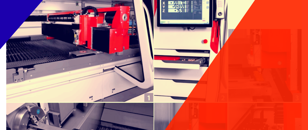
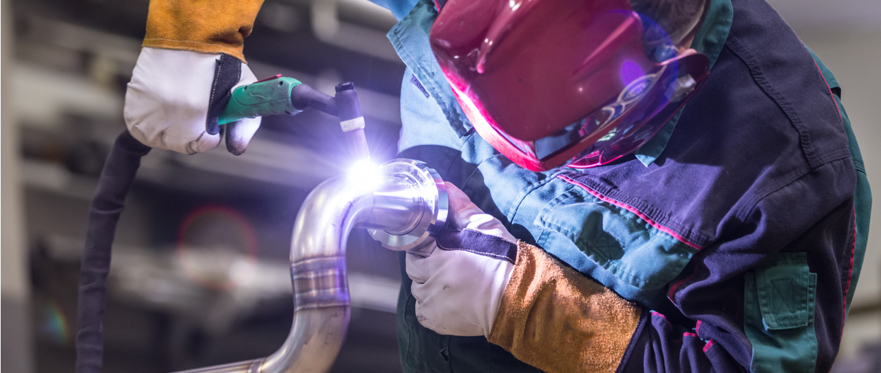
Reverse engineering was the buzz word few years ago. Nowadays, it is not a fancy word anymore. Starting from mechanical sectors up to software companies, Reverse engineering is everywhere. In case you are not caught up with the world recently, reverse engineering is a process where the design and knowledge can be extracted from an existing product in order to preserve and store it or to reproduce it. Since people realized the precision and efficiency of laser cutting in the early 1960s, industrialists are looking for ways to implement this cutting-edge technology to their respective industries. That’s why, from clinical to aerospace use, laser cutting is ruling over metal integrity without raising any questionable eyebrows in case of profit. Laser cutting is usually the first step of the process before it continues down the line to undergo metal bending, metal rolling, and other types of metal fabrication in stainless steel, mild steel and aluminium. In FMB, we only reverse engineering out of production and obsolete components.
Basically, the product is disabled at first (if the product is physical) and then the measurements are noted down. But recently, the manual reverse engineering by hand is losing it charm as softwares are becoming more and more capable of reverse engineering the product digitally.
This is better for many reasons, mainly because it is more accurate. And that’s why it is better to reverse engineer any sheet metal product digitally by creating a 3D model. Here’s how it is done:
Digitally Reverse Engineering Sheet Metal
Reverse engineering any sheet metal product requires 3 things, a 3D model of the metal product, Solidworks, and other related software, and professional skills to get the model right as a CAD file.
Scan the object
The first step towards making a successful flat pallet to understand and know the sheet metal product’s measurement, angle, curves, etc. is to make a good 3D model. 3D scanning is very powerful these days. They can precisely take the measurements of the metal sheet product and contract a 3D model of it. Technologies like computer tomography or industrial CT scanning, structured light digitizers, laser scanners, CMMs, etc. can scan 3D object efficiently. Remember, this important because if the measurements are not correct, there won’t be any use for the next steps.
Using Geomagic Design X
Once you get the scanned 3D model of the sheet metal product, you’ll notice that the model is not quite complete. This is because sheet metal parts usually get distorted by use. Every time they are used, it loses a fraction amount of its integrity. But with Geomagic Design X, you can reverse engineer it and bring back the original shape of that sheet metal part.
Clean up the 3D file
To fill up the distorted region of the metal part and to remove any debris’ 3D print from the 3D model, it should be cleaned up with Geomagic Design X.
Convert into Polygonal Mesh
Once you are done brushing up the 3D model, it is time to convert it into polygonal mesh from point clouds. You can do it by choosing mesh from the left bar below in the Model section.
Auto segmentation of the mesh
By auto segmentation of the polygonal mesh, you get areas made up of similar curvature. This makes it easier to identify and to interrogate geometrical shapes in the 3D model. It can be used to create and establish data on the sheet metal product that you are reverse engineering.
Create real 2D & 3D Geometry
Now you got the basic model for the product. You can now create real 3D and 2D geometry to give the shapes super precision. This way, you will get cleaner edge robust 3D look.
Export the information to a CAD software
By this point, you get all the necessary measurement, angles, and curves of that sheet metal product. You can now use the data from polygonal mesh to create the reverse engineered flat pallet. Simply export the data into a CAD software. IF you were using Solidworks till now, you can continue with that.
Convert the solid model into sheet metal model
Using CAD, convert the solid 3D model of the sheet metal product into a sheet metal model. For that, you need to click on the sheet metal model on the upper side of the left hand corner.
Add required Geometry
Now you can add any required shape if you need any customization to be done with the model.
Validate with Finite Element Analysis
Once you are done reverse engineering the 3D model, you now have to use Finite Element Analysis to validate if the product can take subjected load or not. If you don’t know what Finite Element Analysis, it is a numerical approach to stimulate whether the product can sustain the load forced upon.
Convert the design into Flat pattern
Now everything is done and you have a full 3D design replica of the original sheet metal product. Now you can convert it into a full manufacturing design by clicking “Flatten” on the top menu bar on the right side.
Manually Reverse Engineering Sheet Metal
Reverse engineering of a sheet metal part can be done manually too.
Use delicate tools to measure
The most important part in reverse engineering a sheet metal part is taking the measurements. Even a fraction of a centimeter can ruin the whole structure.
That’s why it’s import that you use delicate tools to measure the product instead of using regular rulers of scales.
Vernier Caliper for Height and width
For measuring the widths and heights of edges, a Vernier caliper would do just fine. The best thing about them is you can measure up to one-twentieth of a millimeter, depending on the number of lines in small scale on it. But make sure the Vernier caliper is error free. Also, it’s better to take the measurement at least 2-3 times. This way, you can evaluate if the data is valid or not.
Screw gauge for measuring the thickness
Once you get the width and height’s measure, you need to get the thickness measured properly. Sometimes the thickness of the product is so thin that a Vernier caliper can be wrong measuring it. In these cases, a screw gauge is the best option to go with. They can measure the thickness precisely, even more than Vernier caliper.
Know the curves and angles
Another aspect of measuring something is the angels and curves. There are a number of ways that you can do it. Choose any one of them that you feel confident about.
Draw out the model
Now draw out the model using approximate ratios of measurements that you took. Make sure you to not down everything in the drawing paper. And now you got the final product design.
Effectiveness of Reverse Engineering Sheet Metal
As it was mentioned earlier, sheet metal products get distorted every time it is used. That’s why there is a chance that you are making out a close replica instead of an absolute copy. This happens mostly if the sheet metal is reverse engineered manually by hand. With the digitally reversed engineered model, the distorted regions can easily be fixed, making the design more accurate and the whole reverse engineering process more effective.


